


In the result tables of the "Stress-Stran Analysis" category, you can open the result details using one of the following options:
- Button
 in the table toolbar
- Double-click in a result row

The "Result Details" dialog box appears. It shows the detailed results and design equations of the stress or stress ratio that apply to the result selected in the table.

You can see detailed results in the central area, and design check formulas in the right column.
Display
In the section on the left, you can specify the parameters of the table row that is selected when opening the dialog box. Thus, you have control over the design situation, governing objects, and stress type.
If you want to check the details of a different case configuration, you can always adjust the parameters in the selection lists – design situation, loading, object, x-location or mesh nodes, design. There are selection options for all calculated result types. For example, if you have only analyzed members, there are no options displayed for member sets and surfaces. Furthermore, you cannot switch to the member design checks in the Design Check Details of surfaces. In this case, select the corresponding result table in the program without closing the "Result Details" dialog box.
If you want to check the results of another object, you can remove the member or surface by clicking the
![]() button in the work window.
button in the work window.
For the results of a member set, only the member numbers belonging to this member set are available for selection in the list of members. When activating the
![]() button for a member set, the "Member Location x" refers to the start of the member set. If it is inactive, the x-location refers to the start of the selected member. The members designed without a member set are available in the list if you select the "--" entry for "Member Set No."
button for a member set, the "Member Location x" refers to the start of the member set. If it is inactive, the x-location refers to the start of the selected member. The members designed without a member set are available in the list if you select the "--" entry for "Member Set No."
Result Details
The main input parameters, intermediate values, and analysis results are listed in a tree structure in the main area of the Details tab. This allows you to follow the stresses and stress ratios determined in detail.
Stresses by Stress Point / Stresses in Mesh Node
The second tab allows for a targeted evaluation of results for the member or surface location. The content depends on whether the stresses of a member or a surface are displayed.
For member results, the stresses are listed in the individual stress points of the cross-section.
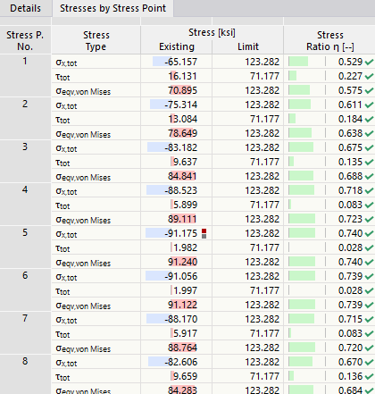
The stress points are explained in the chapter Stresses on Members .
For surface results, the stresses in the surface cross-section are listed: top, middle, or bottom.
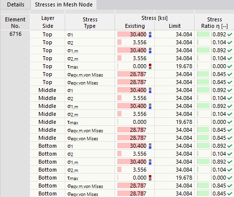
If you have defined a surface using layer elements with the Multilayer Surfaces add-on, the surface stresse of each layer are displayed.
Design Check Formulas
The right section shows the essential formulas for determining stresses and stress ratios.
You can also use the design formulas in the documentation. The
![]() list button provides you with various printout options.
list button provides you with various printout options.
Menu "View" and "Options"
The "Result Details" dialog box provides the menu functions to open further dialog boxes in order to evaluate the results or to control the view. As an alternative, you can use the corresponding buttons. The buttons have the following functions:
| Button | Function |
|---|---|
|
|
Synchronize result details with the selected objects in the table |
|
|
Synchronize the result table with the selection of result details |
|
|
Display or hide the colored relation scales in the Stresses by Stress Point or Stresses in Mesh Node tab |
|
|
Open a window with the information about material properties |
|
|
Open a window with the information about cross-section properties |
|
|
Opens a window with the information about the layer structure of the surface |
|
|
Open the Stress Distribution in Section window |
|
|
Open the Result Diagrams in Surface Point window |
|
|
Open the Result Diagrams dialog box |