94 Results
View Results:
Sort by:

The fatigue design according to EN 1992-1-1 must be performed for the structural components subjected to large stress ranges and/or many load changes. In this case, the design checks for the concrete and the reinforcement are performed separately. There are two alternative design methods available.

The automatic surface reinforcement design process determines a surface reinforcement that covers the required amount of reinforcement.

If you want to use a pure surface model, for example, when determining the internal forces and moments, but the structural component is still designed on the member model, you can take advantage of a result beam.
![Spans Based on Figure 5.2 from [1]](/en/webimage/039540/3493372/01_Abmessungen_EN.png?mw=640&hash=a3c436931baff3514db261b2d11bfa39abae9170)
In order to correctly design a downstand beam or a T-beam in RFEM 6 using the Concrete Design add-on, it is essential to determine the flange widths for the rib members. This article describes the input options for a two-span beam and the calculation of the flange dimensions according to EN 1992-1-1.

- 001819
- Design
- Aluminum Design for RFEM 6
-
- Aluminum Design for RSTAB 9
- Concrete Design for RFEM 6
- Concrete Design for RSTAB 9
- Steel Design for RFEM 6
- Steel Design for RSTAB 9
- Timber Design for RFEM 6
- Timber Design for RSTAB 9
- Concrete Structures
- Steel Structures
- Timber Structures
- Structural Analysis & Design
- Eurocode 0
- Eurocode 2
- Eurocode 3
- Eurocode 5
- Eurocode 9
- ADM
- ANSI/AISC 360
For the serviceability of a structure, the deformations must not exceed certain limit values. This article describes an example that shows how to analyze the deflection of members using Dlubal's design add-ons.

The optimal scenario in which punching shear design according to ACI 318-19 [1] or CSA A23.3:19 [2] should be utilized is when a slab is experiencing a high concentration of loading or reaction forces occurring at one single node. In RFEM 6, the node in which punching shear is an issue is referred to as a punching shear node. The causes of these high concentration of forces can be introduced by a column, concentrated force, or nodal support. Connecting walls can also cause these concentrated loads at wall ends, corners, and ends of line loads and supports.

In accordance with Sect. 6.6.3.1.1 and Clause 10.14.1.2 of ACI 318-19 and CSA A23.3-19, respectively, RFEM effectively takes into consideration concrete member and surface stiffness reduction for various element types. Available selection types include cracked and uncracked walls, flat plates and slabs, beams, and columns. The multiplier factors available within the program are taken directly from Table 6.6.3.1.1(a) and Table 10.14.1.2.

The punching shear design, in line with EN 1992-1-1, should be performed for slabs with a concentrated load or reaction. The node where the design of punching shear resistance is performed (that is, where there is a punching problem) is called a node of punching shear. The concentrated load at these nodes can be introduced by columns, concentrated force, or nodal supports. The end of the linear load introduction on slabs is also regarded as a concentrated load and therefore, the shear resistance at wall ends, wall corners, and ends or corners of line loads and line supports should be controlled as well.

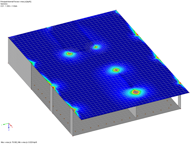
This article describes how a flat slab of a residential building is modeled in RFEM 6 and designed according to Eurocode 2. The plate is 24 cm thick and is supported by 45/45/300 cm columns at distances of 6.75 m in both the X and Y directions (Image 1). The columns are modeled as elastic nodal supports by determining the spring stiffness based on the boundary conditions (Image 2). C35/45 concrete and B 500 S (A) reinforcing steel are selected as the materials for the design.

This article compares the design to the one in the referenced article: Design of Concrete Columns Subjected to Axial Compression with RF-CONCRETE Members. It is, therefore, about taking exactly the same theoretical application carried out in RF-CONCRETE Members and reproducing it in RF-CONCRETE Columns. Thus, the objective is to compare the different input parameters and the results obtained by the two add-on modules for the design of column-like concrete members.

This article deals with rectilinear elements of which the cross-section is subjected to axial compressive force. The purpose of this article is to show how very many parameters defined in the Eurocodes for concrete column calculation are considered in the RFEM 5 structural analysis software.

This article deals with the determination of the concrete reinforcement for a beam stressed by tension only according to EN 1992-1-1. The aim is to show the tensile load of a member-type element (without imposed deformations) and to define the concrete reinforcement in accordance with the standard's construction rules and provisions using the RFEM structural analysis software.
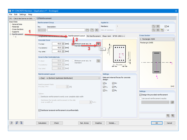
This article deals with the protection of reinforcement against corrosion defined according to EN 1992-1-1, also called concrete cover. The purpose of this article is to show how very many parameters defined in the Eurocodes for concrete reinforcements are considered in the RFEM structural analysis software.

This article deals with elements concerning which the cross-section is subjected simultaneously to a bending moment, a shear force, and an axial compressive or tensile force. However, in our example we will not include loading due to shear force.

You can model and analyze masonry structures in RFEM 6 with the Masonry Design add-on that employs the finite element method for the design. Complex masonry structures can be modeled, and static and dynamic analysis can be performed, given that a nonlinear material model is implemented in the program to display the load-bearing behavior of masonry and the different failure mechanisms. You can enter and model masonry structures directly in RFEM 6 and combine the masonry material model with all common RFEM add-ons. In other words, you can design entire building models in connection with masonry.

According to EN 1992-1-1 [1], a beam is a member of which the span is no less than 3 times the overall section depth. Otherwise, the structural element should be considered as a deep beam. The behavior of deep beams (that is, beams with a span less than 3 times the section depth) is different from the behavior of normal beams (that is, beams with a span that is 3 times greater than the section depth).
However, designing deep beams is often necessary when analyzing the structural components of reinforced concrete structures, since they are used for window and door lintels, upstand and downstand beams, the connection between split-level slabs, and frame systems.

To perform deflection analysis in the right manner, it is important to “inform” the program about the exact support conditions of the element of interest. The definition of design supports in RFEM 6 will be shown for a reinforced concrete member set.

Describing the procedure for the serviceability limit state design of a floor slab made of steel fiber reinforced concrete. This article shows how to perform the corresponding design for the SLS by means of the iteratively determined FEA results.

Reinforced concrete surface design for slabs, plates, and walls is possible in the RF-CONCRETE Surfaces module according to the ACI 318-19 or the CSA A23.3-19 standard. A common approach for slab design is the use of design strips for determining the average one-way internal forces over the width of the strip. This design strip method essentially takes a two-way slab element and applies a simpler one-way approach to determine the required reinforcement needed along the strip length.

According to Book 631 of the DAfStb (German Committee for Structural Concrete), Chapter 2.4, the structural behavior of ceilings changes if their continuous support by walls is interrupted in areas of openings. Depending on the length of the opening area and the plate thickness, measures are necessary regarding the analysis of the ceiling in the area of the opening.
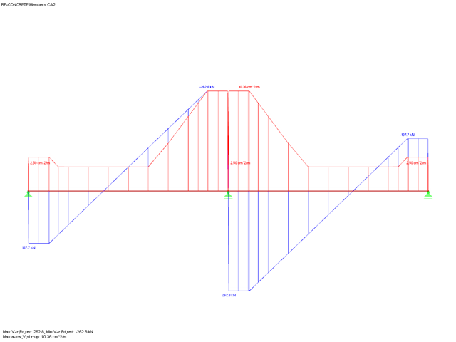
When performing shear force design in RF-CONCRETE Members and CONCRETE, you can reduce the acting shear force Vz according to EN 1992-1-1. The following article describes the reduction of the concentrated loads close to the support and the shear force design at the distance d from the support face for a uniform load.
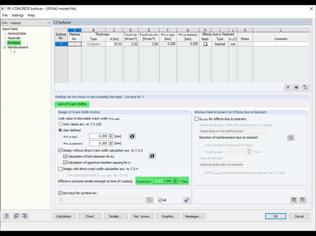
Eurocode 2 provides two ways to perform a crack width design. On one hand, the crack width design according to 7.3.3 can be performed without direct calculation by means of tables for the limitation of the member spacing and diameter. On the other hand, the crack width wk can be determined directly according to 7.3.4 and compared to a limit value.
In RF-PUNCH Pro, you can perform the punching shear design on wall corners and wall ends. The basis for the design is the punching load, which is automatically determined from the RFEM internal forces in the connected surface. Since the surface internal forces from the RFEM calculation may be subject to the influence of singularity locations, this can also have a negative influence on the determined punching load at the wall corner or end. This article describes possible optimization options that you can use to minimize this unfavorable influence.

If a rib is part of a nonlinear design or is rigidly connected to following walls, a surface should be used for the modeling instead of a member. So that the rib can still be designed as a member, a result member with the correct eccentricity is required, which transforms the surface internal forces into member internal forces.

Steel-fiber-reinforced concrete is mainly used nowadays for industrial floors or hall floors, foundation plates with low loads, basement walls, and basement floors. Since the publication in 2010 of the first guideline about steel-fiber-reinforced concrete by the German Committee for Reinforced Concrete (DAfStb), a structural engineer can use standards for the design of the steel fiber-reinforced concrete composite material, which makes the use of fiber-reinforced concrete increasingly popular in construction. This article describes the nonlinear calculation of a foundation plate made of steel fiber-reinforced concrete in the ultimate limit state with the FEA software RFEM.
When determining the minimum reinforcement for the serviceability limit state according to 7.3.2, the applied effective tensile strength fct,eff has a significant influence on the determined amount of reinforcement. The following article gives an overview about determining the effective tensile strength fct,eff and the input options in RF-CONCRETE.

In RF-PUNCH Pro, enlarged column heads can be arranged at point-supported punching shear points, thus increasing the shear force resistance of a reinforced concrete floor. In the following article, we will show the punching shear design with the optional application of an enlarged column head.

Determining the Material Properties of Steel-Fiber-Reinforced Concrete and Their Application in RFEM
Steel-fiber-reinforced concrete is mainly used nowadays for industrial floors or hall floors, foundation plates with low loads, basement walls, and basement floors. Since the publication in 2010 of the first guideline about steel-fiber-reinforced concrete by the German Committee for Reinforced Concrete (DAfStb), a structural engineer can use standards for the design of the steel fiber-reinforced concrete composite material, which makes the use of fiber-reinforced concrete increasingly popular in construction. This article explains the individual material parameters of steel-fiber-reinforced concrete and how to deal with these material parameters in the FEM program RFEM.

When modeling a reinforced concrete rib with a masonry wall above, there is the risk that the rib is underdesigned if the structural behavior of the masonry is not correctly considered and the connection between the masonry wall and downstand beam is not modeled sufficiently accurately. This article deals with this issue and shows the possible modeling options of such a structure. In this example, the reinforcement is determined only from the internal forces and without secondary minimum reinforcement.

RF-PUNCH Pro performs punching shear design on concentrated load application locations (column connection, nodal support, and nodal load) as well as on wall ends and wall corners.