60 Results
View Results:
Sort by:

Lateral-Torsional Buckling (LTB) is a phenomenon that occurs when a beam or structural member is subjected to bending and the compression flange is not sufficiently supported laterally. This leads to a combination of lateral displacement and twisting. It is a critical consideration in the design of structural elements, especially in slender beams and girders.

The three types of moment frames (Ordinary, Intermediate, Special) are available in the Steel Design add-on of RFEM 6. The seismic design result according to AISC 341-22 is categorized into two sections: member requirements and connection requirements.

The Steel Design add-on in RFEM 6 now offers the ability to perform seismic design according to AISC 341-16 and AISC 341-22. Five types of seismic force-resisting systems (SFRS) are currently available.

The three types of moment frames (Ordinary, Intermediate, Special) are available in the Steel Design add-on of RFEM 6. The seismic design result according to AISC 341-16 is categorized into two sections: member requirements and connection requirements.

Moment frame design according to AISC 341-16 is now possible in the Steel Design add-on of RFEM 6. The seismic design result is categorized into two sections: member requirements and connection requirements. This article covers the required strength of the connection. An example comparison of the results between RFEM and the AISC Seismic Design Manual [2] is presented.

The design of an Ordinary Concentrically Braced Frame (OCBF) and a Special Concentrically Braced Frame (SCBF) can be carried out in the Steel Design add-on of RFEM 6. The seismic design result according to AISC 341-16 and 341-22 is categorized into two sections: Member Requirements and Connection Requirements.

Plate girder is an economical choice for long spans construction. I-section steel plate girder typically has a deep web to maximize its shear capacity and flange separation, yet thin web to minimize the self-weight. Due to its large height-to-thickness (h/tw) ratio, transverse stiffeners may be required to stiffen the slender web.

The automatic surface reinforcement design process determines a surface reinforcement that covers the required amount of reinforcement.

- 001819
- Design
- Aluminum Design for RFEM 6
-
- Aluminum Design for RSTAB 9
- Concrete Design for RFEM 6
- Concrete Design for RSTAB 9
- Steel Design for RFEM 6
- Steel Design for RSTAB 9
- Timber Design for RFEM 6
- Timber Design for RSTAB 9
- Concrete Structures
- Steel Structures
- Timber Structures
- Structural Analysis & Design
- Eurocode 0
- Eurocode 2
- Eurocode 3
- Eurocode 5
- Eurocode 9
- ADM
- ANSI/AISC 360
For the serviceability of a structure, the deformations must not exceed certain limit values. This article describes an example that shows how to analyze the deflection of members using Dlubal's design add-ons.

Custom sections are often required in cold-formed steel design. In RFEM 6, the custom section can be created using one of the “Thin-Walled” sections available in the library. For other sections that do not meet any of the 14 available cold-formed shapes, the sections can be created and imported from the standalone program, RSECTION. For general information on AISI steel design in RFEM 6, refer to the Knowledge Base article provided at the end of the page.

The design of cold-formed steel members according to the AISI S100-16 is now available in RFEM 6. Design can be accessed by selecting “AISC 360” as the standard in the Steel Design add-on. “AISI S100” is then automatically selected for the cold-formed design (Image 01).

The Steel Joist Institute (SJI) previously developed Virtual Joist tables to estimate the section properties for Open Web Steel Joists. These Virtual Joist sections are characterized as equivalent wide-flange beams which closely approximate the joist chord area, effective moment of inertia, and weight. Virtual Joists are also available in the RFEM and RSTAB cross-section database.

Windbreak structures are special types of fabric structures which protect the environment from harmful chemical particles, abate wind erosion, and help to maintain valuable sources. RFEM and RWIND are used for wind-structure analysis as one-way fluid-structure interaction (FSI).
This article demonstrates how to structural design windbreak structures using RFEM and RWIND.

This article discusses the options available for determining the nominal flexural strength, Mnlb for the limit state of local buckling when designing according to the 2020 Aluminum Design Manual.

A standard scenario in timber member construction is the ability to connect smaller members by means of bearing on a larger girder member. Additionally, member end conditions may include a similar situation where the beam is bearing on a support type. In either scenario, the beam must be designed to consider the bearing capacity perpendicular to the grain according to NDS 2018 Sec. 3.10.2 and CSA O86:19 Clauses 6.5.6 and 7.5.9. In general structural design software, it is typically not possible to carry out this full design check, as the bearing area is unknown. However, in the new generation RFEM 6 and Timber Design add-on, the added 'design supports' feature now allows users to comply with the NDS and CSA bearing perpendicular to the grain design checks.

The optimal scenario in which punching shear design according to ACI 318-19 [1] or CSA A23.3:19 [2] should be utilized is when a slab is experiencing a high concentration of loading or reaction forces occurring at one single node. In RFEM 6, the node in which punching shear is an issue is referred to as a punching shear node. The causes of these high concentration of forces can be introduced by a column, concentrated force, or nodal support. Connecting walls can also cause these concentrated loads at wall ends, corners, and ends of line loads and supports.

You can model and analyze masonry structures in RFEM 6 with the Masonry Design add-on that employs the finite element method for the design. Complex masonry structures can be modeled, and static and dynamic analysis can be performed, given that a nonlinear material model is implemented in the program to display the load-bearing behavior of masonry and the different failure mechanisms. You can enter and model masonry structures directly in RFEM 6 and combine the masonry material model with all common RFEM add-ons. In other words, you can design entire building models in connection with masonry.

The AISC 360-16 steel standard requires stability consideration for a structure as a whole and each of its elements. Various methods for this are available, including direct consideration in the analysis, the effective length method, and the direct analysis method. This article will highlight the important requirements from Ch. C [1] and the direct analysis method to be incorporated in a structural steel model along with the application in RFEM 6.

Defining the appropriate effective length is crucial in obtaining the correct member design capacity. For X-bracing that is connected at the center, engineers often wonder if the full end-to-end length of the member shall be used, or whether using half of the length to where the members are connected is sufficient. This article outlines the recommendations given by the AISC and provides an example on how to specify the effective length of the X-braces in RFEM.

In accordance with Sect. 6.6.3.1.1 and Clause 10.14.1.2 of ACI 318-19 and CSA A23.3-19, respectively, RFEM effectively takes into consideration concrete member and surface stiffness reduction for various element types. Available selection types include cracked and uncracked walls, flat plates and slabs, beams, and columns. The multiplier factors available within the program are taken directly from Table 6.6.3.1.1(a) and Table 10.14.1.2.

The stability checks for the equivalent member design according to EN 1993-1-1, AISC 360, CSA S16, and other international standards require consideration of the design length (that is, the effective length of the members). In RFEM 6, it is possible to determine the effective length manually by assigning nodal supports and effective length factors or, on the other hand, by importing it from the stability analysis. Both options will be demonstrated in this article by determining the effective length of the framed column in Image 1.

Blast loads from high-energy explosives, either accidental or intentional, are rare but may be a structural design requirement. These dynamic loads differ from standard static loads due to their large magnitude and very short duration. A blast scenario can be carried out directly in an FEA program as a time history analysis to minimize loss of life and evaluate varying levels of structural damage.

In the RF-/TIMBER Pro, RF-/TIMBER AWC, and RF-/TIMBER CSA add-on modules, you can consider the resulting deformation of a member or set of members. In addition to the local directions y and z, you have the option "R." This allows you to compare the total deflection of a girder to the limit values given in the standards.

Besides the standardized gamma method, you can display the semi-rigid composite beams also as a framework model.

For a timber connection as shown in Figure 01, you can take into account the torsional spring rigidity (spring stiffness for rotation) of the connections. You can determine it by means of the slip modulus of the fastener and the polar moment of inertia of the connection.

For the design of concrete surfaces, the rib component of the internal forces can be neglected for the ULS calculation and for the analytical method of the SLS calculation, because this component is already considered in the member design. To do this, select the check box in the "Details" dialog box. If no rib was defined, this function is not available.
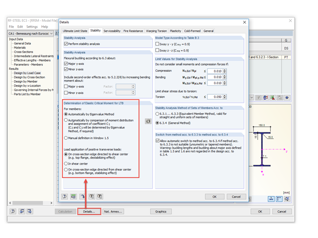
Occasionally, the question arises how to determine the correct load application point of the positive transverse loads in RF-/STEEL EC3 and RF-/STEEL AISC.

RF-CONCRETE Members for RFEM or CONCRETE for RSTAB propose an automatically created reinforcement to the user if the "Design the provided reinforcement" option is selected in Window 1.6 "Reinforcement".
.png?mw=640&hash=8fd04a597cecae2e434980ce79fc626815a5d98a)
The Aluminum Design Manual (ADM) 2020 was released in February 2020. The ADM 2020 gives guidance for both the allowable strength design (ASD) and load and resistance factor design (LRFD) for aluminum members to ensure reliability and safety for all aluminum structures. This latest standard was integrated in the RFEM/RSTAB add-on module RF-/ALUMINUM ADM. The text below will highlight the applicable updates relevant to the Dlubal programs.

In the case of open cross-sections, the torsional load is removed mainly via secondary torsion, since the St. Venant torsional stiffness is low compared to the warping stiffness. Therefore, warping stiffeners in the cross-section are particularly interesting for the lateral-torsional buckling analysis, as they can significantly reduce the rotation. For this, end plates or welded stiffeners and sections are suitable.