38 Results
View Results:
Sort by:

- 001819
- Design
- Aluminum Design for RFEM 6
-
- Aluminum Design for RSTAB 9
- Concrete Design for RFEM 6
- Concrete Design for RSTAB 9
- Steel Design for RFEM 6
- Steel Design for RSTAB 9
- Timber Design for RFEM 6
- Timber Design for RSTAB 9
- Concrete Structures
- Steel Structures
- Timber Structures
- Structural Analysis & Design
- Eurocode 0
- Eurocode 2
- Eurocode 3
- Eurocode 5
- Eurocode 9
- ADM
- ANSI/AISC 360
For the serviceability of a structure, the deformations must not exceed certain limit values. This article describes an example that shows how to analyze the deflection of members using Dlubal's design add-ons.

In RFEM 6, the results for the FE mesh nodes are determined using the finite element method. For the distribution of internal forces, deformations, and stresses to be continuous, these nodal values are smoothed through an interpolation process. This article will introduce and compare the different types of smoothing that you can use for this purpose.

In the RF-/TIMBER Pro, RF-/TIMBER AWC, and RF-/TIMBER CSA add-on modules, you can consider the resulting deformation of a member or set of members. In addition to the local directions y and z, you have the option "R." This allows you to compare the total deflection of a girder to the limit values given in the standards.

By means of result combinations, it is possible to create, among other things, the envelopes for internal forces and deformations. Thus, you can quickly find the maxima and minima for the subsequent design.

This article deals with the determination of the concrete reinforcement for a beam stressed by tension only according to EN 1992-1-1. The aim is to show the tensile load of a member-type element (without imposed deformations) and to define the concrete reinforcement in accordance with the standard's construction rules and provisions using the RFEM structural analysis software.

In the case of wall-like load-bearing behavior of the cross-laminated timber plate, special attention must be paid to the shear deformation in the plane of the pane and thus, in particular, to the displaceability of the fasteners.
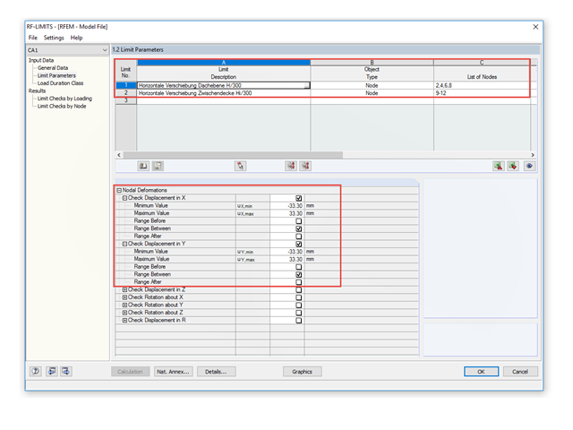
To control the lateral displacements of a model, you can use the RF-/LIMITS add‑on module. This add‑on module allows you to, for example, run a serviceability limit state analysis to find horizontal nodal deformations and to set it against a limit value.

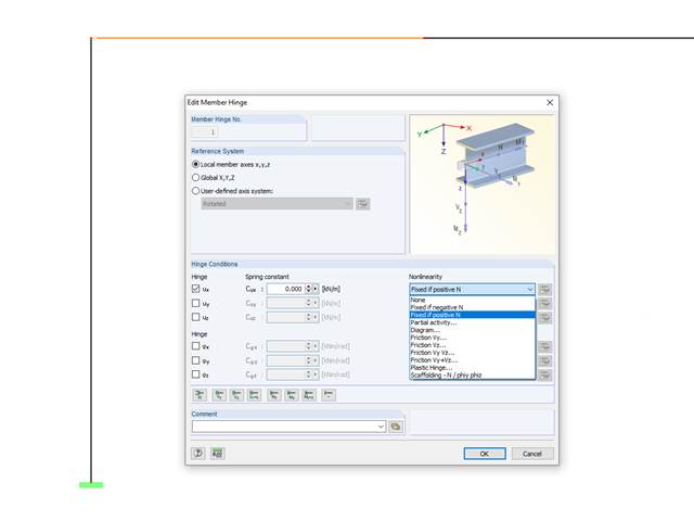
In RFEM 5 and RSTAB 8, it is possible to assign nonlinearities to member hinges. In addition to the nonlinearities "Fixed if" and "Partial activity", you can select "Diagram". If you select the "Diagram" option, you have to specify the according settings for the activity of the member hinge. For the individual definition points, it is necessary to specify the abscissa and ordinate values (deformations or rotations and the according internal forces) that define the hinge.

Shrinkage and creep are time-dependent deformation properties of concrete that usually have to be considered in the serviceability limit state design.
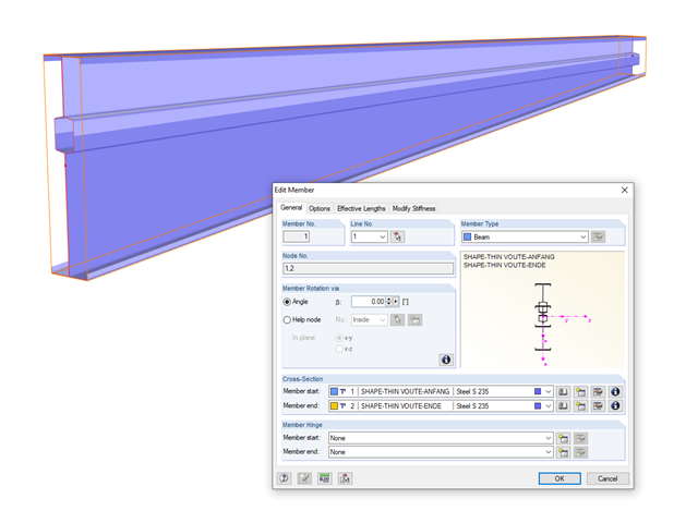
In RFEM and RSTAB, you can analyze members with a variable cross-section, which can also consist of freely defined SHAPE-THIN cross-sections. The cross-section properties are interpolated in order to determine the internal forces and deformations.
In RFEM and RSTAB, it is possible to define nonlinear properties of member releases. In addition to the activity diagrams and force-deformation relationship, you also have the simple option of using signs or limit values of the internal forces as criteria for the effectiveness of the release. This way, you can specify which internal forces should be transferred at the member end.

This technical article deals with the design of structural components and cross-sections of a welded truss girder in the ultimate limit state. Furthermore, the deformation analysis in the serviceability limit state is described.

The elastic deformations of a structural component due to a load are based on Hooke's law, which describes a linear stress-strain relation. They are reversible: After the relief, the component returns to its original shape. However, plastic deformations lead to irreversible deformations. The plastic strains are usually considerably larger than the elastic deformations. For plastic stresses of ductile materials such as steel, yielding effects occur where the increase in deformation is accompanied by hardening. They lead to permanent deformations - and in extreme cases to the destruction of the structural component.
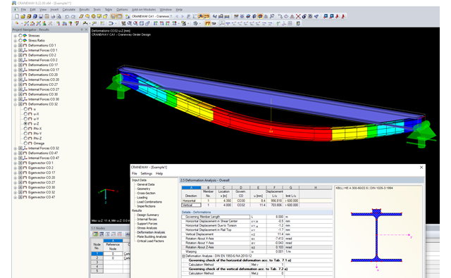
This article describes the different options for determining the allowable deformation of crane runway girders. Since multi-span beams and flexible lateral supports (sway bracing) are used in practice, this article will show how to select the correct method.
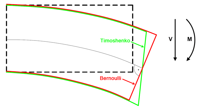
In current literature, the formulas used to determine internal forces and deformations manually are usually specified without considering the shear deformation. The deformations resulting from shear force are often underestimated in timber construction in particular.

Different methods are available for calculating the deformation in the cracked state. RFEM provides an analytical method according to DIN EN 1992-1-1 7.4.3 and a physical-nonlinear analysis. Both methods have different features and can be more or less suitable depending on the circumstances. This article will give an overview of the two calculation methods.
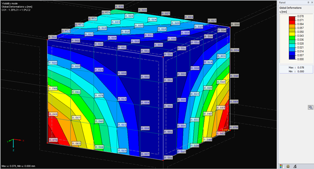
The deformations of the FE nodes are always the first result of an FE calculation. It is possible to calculate strains, internal forces, and stresses based on these deformations and the stiffness of the elements.
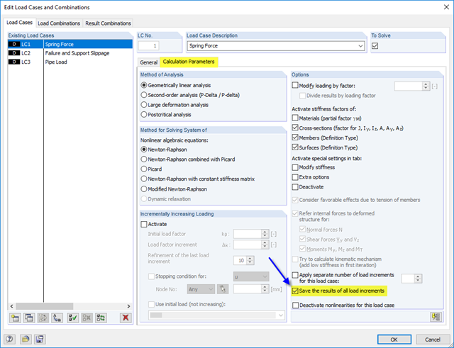
The calculation in RFEM is usually carried out in several calculation steps (iterations). It is then possible to consider particular characteristics of the model, such as objects with nonlinear functions. In addition, by using the iterative calculation, nonlinear effects are taken into account that result from changes in deformation and internal forces in case of the second-order analysis or when considering large deformations (cable theory). In case of complex models, geometric linear calculations are usually insufficient.
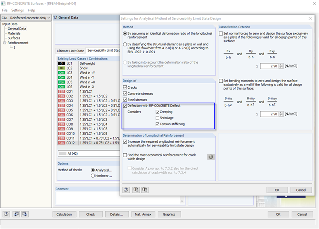
Performing serviceability limit state design also includes taking into account the allowable deformation. Calculating the deformation of reinforced concrete components depends on whether or not the observed cross-section cracks under the applied loading. The governing control parameter in RF-CONCRETE Deflect is the distribution coefficient ζ.

The story drift of a building provides valuable information about its structural behavior under seismic loads. These could cause large horizontal deformations and even instabilities. Some standards, therefore, call for a check of the story drift in its center of gravity. It indicates, for example, if a second-order analysis (P-Δ effect) is necessary.
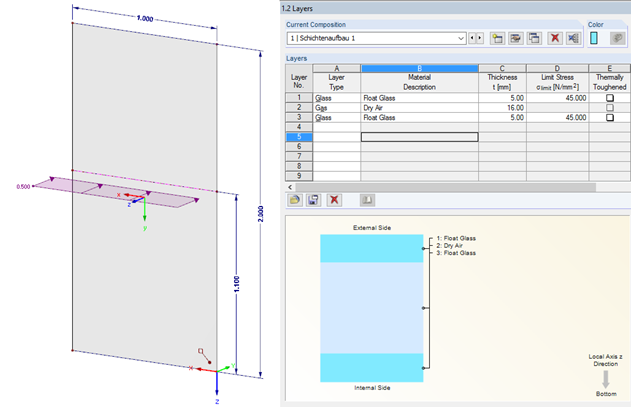
The proportion of glass used when planning a building is increasing. Open, light-flooded buildings represent the modern art of architecture. However, specialized engineers have to face new challenges during planning. One such example is ceiling-high glass facades loaded by a handrail. The influence of this loading, as well as the calculation of the deformation, are shown in this article.
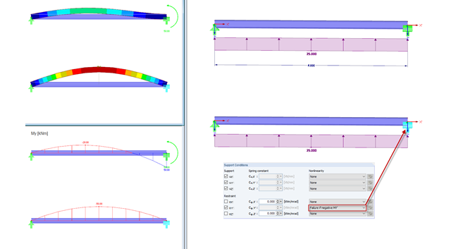
In practice, an engineer often faces the task of representing the support conditions as close to the reality as possible in order to be able to analyze the deformations and internal forces of the structure subjected to their influence and to enable construction that is as cost efficient as possible. RFEM and RSTAB provide numerous options for defining nonlinear nodal supports. This second part describes the options for creating a nonlinear support for a restraint and provides a simple example. For a better understanding, the result is always compared to a linearly defined support.
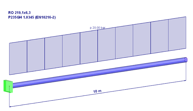
Piping systems are exposed to a variety of loads. One of the most decisive is internal pressure. This article will, therefore, deal with the stresses and deformations resulting from a pure internal compression load in the pipe wall or for the pipe.
When designing reinforced concrete components according to EN 1992‑1‑1 [1], nonlinear methods of determining internal forces for the ultimate and serviceability limit states are possible. In this case, the internal forces and deformations are determined with respect to their nonlinear behaviour. The analysis of stresses and strains in cracked state usually provides the deflections, which clearly exceed the linearly determined values.
RFEM and the RF-CONCRETE add-on modules provide various options for the deformation analysis of a T-beam in the cracked state (state II). This technical article describes the calculation methods (C) and modeling options (M). Both the calculation methods and the modeling options are not limited to T-beams, but will only be explained using this system as an example.
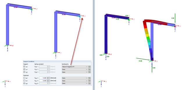
In practice, an engineer often faces the task of representing the support conditions as close to the reality as possible in order to be able to analyze the deformations and internal forces of the structure subjected to their influence, and to enable construction that is as cost-effective as possible. RFEM and RSTAB provide numerous options for defining nonlinear nodal supports. The first section of my article describes the options for creating a nonlinear free support and provides a simple example. For a better understanding, the result is always compared to a linearly defined support.
Buildings must be designed and dimensioned in the way that both vertical and horizontal loads are conducted safely and without large deformations in the building. Examples of horizontal loads are wind, unintentional inclination, earthquake, and a blast.
![System and Loading According to [1]](/en/webimage/009634/2419765/01-en-png-png.png?mw=640&hash=5e657e3feb5c1bb6d21727468dd85d91e1c9f29f)
A structural analysis does not only determine and design internal forces and deformations. It also ensures that the forces and moments in a structure are generated in a reliable way and applied to the foundation. Dlubal Software provides a wide range of products for the structural analysis and design of steel and timber connections. The RF-/JOINTS Steel – Column Base add-on module allows you to design footings of hinged and restrained column bases. The design can be performed for column base plates with or without stiffeners.
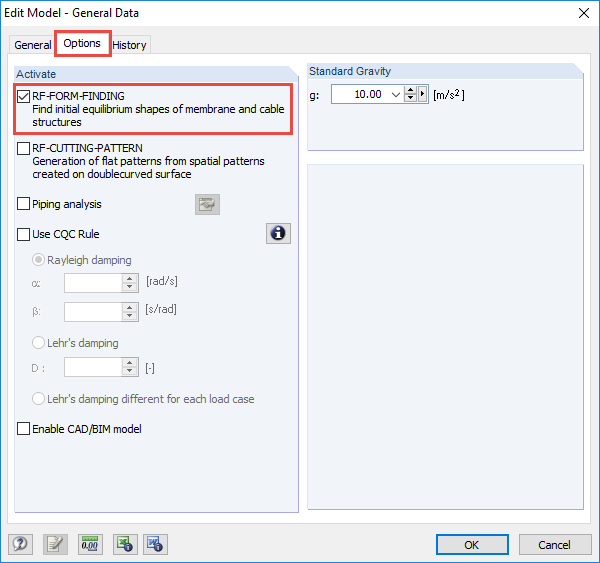
The RF-FORM-FINDING add-on module determines equilibrium shapes of membrane and cable elements in RFEM. In this calculation process, the program searches for such geometric position where the surface stress/prestress of membranes and cables is in equilibrium with natural and geometric boundary conditions. This process is called form-finding (hereinafter referred to as FF). The FF calculation can be activated in RFEM globally in the "General Data" of a model, "Options" tab. After selecting the corresponding option, a new load case or a calculation process called RF-FORM-FINDING is created in RFEM. An additional FF parameter is available for defining surface stress and prestress when entering cables and membranes. By activating the FF option, the program always starts the form-finding process before the pure structural calculation of internal forces, deformation, eigenvalues, etc., and generates a corresponding prestressed model for further analysis.
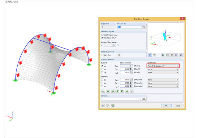
During the form-finding process, the slip modulus of a substructure is also taken into account when searching for the equilibrium state. You can also consider large deflections of supporting trusses or pure bending deformation of the edge beams when determining the membrane shape.