51 Results
View Results:
Sort by:

Using the Timber Design add-on, timber column design is possible according to the 2018 NDS standard ASD method. Accurately calculating timber member compressive capacity and adjustment factors is important for safety considerations and design. The following article will verify the maximum critical buckling strength calculated by the Timber Design add-on using step-by-step analytical equations as per the NDS 2018 standard including the compressive adjustment factors, adjusted compressive design value, and final design ratio.

The data exchange between RFEM 6 and Allplan can be done using various file formats. This article describes the data exchange of a determined surface reinforcement using the ASF interface. This allows you to display the RFEM reinforcement values as level curves or colored reinforcement images in Allplan.

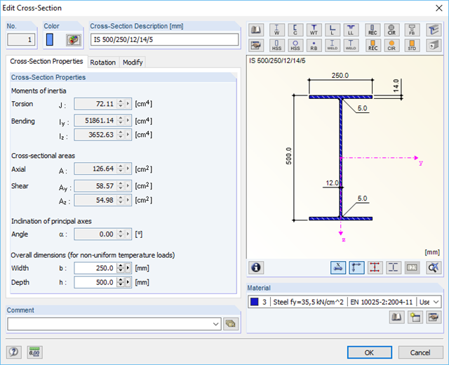
Plate girder is an economical choice for long spans construction. I-section steel plate girder typically has a deep web to maximize its shear capacity and flange separation, yet thin web to minimize the self-weight. Due to its large height-to-thickness (h/tw) ratio, transverse stiffeners may be required to stiffen the slender web.

In order to be able to carry out a pushover analysis, it is necessary to transform the determined capacity curve into a simplified form. The N2 method is described in Eurocode EN 1998. This article should help to explain what a bilinearization according to the N2 method involves.

In this article, a lap joint of a ZL purlin on a monopitch roof is modeled and designed using the Steel Joints add-on, and compared with the load-bearing capacity table of the manufacturer.

With the Steel Design add-on, you can design structural steel components in the event of fire using the simple design methods according to Eurocode 3. The component temperature at the time of the design check can be determined automatically according to the temperature-time curves specified in the standard. In addition to considering a cladding for fire protection, it is also possible for you to take account of the beneficial properties of hot-dip galvanization.

A standard scenario in timber member construction is the ability to connect smaller members by means of bearing on a larger girder member. Additionally, member end conditions may include a similar situation where the beam is bearing on a support type. In either scenario, the beam must be designed to consider the bearing capacity perpendicular to the grain according to NDS 2018 Sec. 3.10.2 and CSA O86:19 Clauses 6.5.6 and 7.5.9. In general structural design software, it is typically not possible to carry out this full design check, as the bearing area is unknown. However, in the new generation RFEM 6 and Timber Design add-on, the added 'design supports' feature now allows users to comply with the NDS and CSA bearing perpendicular to the grain design checks.

The design of cross-sections according to Eurocode 3 is based on the classification of the cross-section to be designed in terms of classes determined by the standard. The classification of cross-sections is important, since it determines the limits of resistance and rotation capacity due to local buckling of cross-section parts.

Defining the appropriate effective length is crucial in obtaining the correct member design capacity. For X-bracing that is connected at the center, engineers often wonder if the full end-to-end length of the member shall be used, or whether using half of the length to where the members are connected is sufficient. This article outlines the recommendations given by the AISC and provides an example on how to specify the effective length of the X-braces in RFEM.

The reinforced concrete design for fire situations is carried out according to the simplified method based on EN 1992-1-2, Clause 4.2. The "zone method" described in Annex B.2 is used: The cross-section is subdivided into a number of parallel zones of equal thickness, and their temperature-dependent compressive strength is determined. The reduced load-bearing capacity in the event of fire exposure is thus represented by a reduced structural component's cross-section with reduced strengths.

In RFEM, you can display the contact properties between two surfaces by means of contact solids.

The RF-/LIMITS add-on module allows you to compare the ultimate limit state of members, member ends, nodes, nodal supports, and surfaces (RFEM only) by means of a defined ultimate load capacity. Furthermore, you can check nodal displacements and cross-section dimensions. In this example, the column bases of a carport are to be compared with the maximum allowable forces specified by the manufacturer.
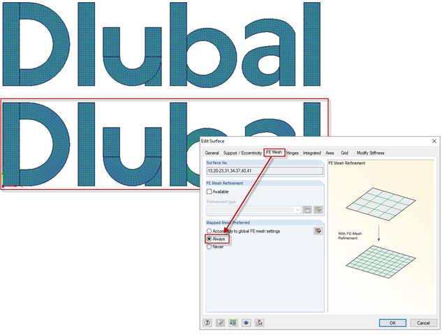
The "Mapped Mesh Preferred" option has an influence on the mesh generation of surfaces with curved and folded outlines. The program tries to align the FE mesh with the boundary lines of the surfaces.

The RF‑/STEEL EC3 add-on module automatically transfers the buckling line to be used for the flexural buckling analysis for a cross-section from the cross-section properties. The assignment of the buckling line can be adjusted manually in the module input for general cross-sections in particular, as well as for special cases.

For cross‑laminated structures with large spans, downstand beams or hybrid structures are often used. They can be modeled in RFEM 5 by using surfaces and member cross‑sections. In both structural systems, curved downstand beams are also possible without any problems. In the case of the curved surface, the member is always appropriately generated by means of the automatic member eccentricity with the thickness distance of the surface and the member. The downstand beam can also be connected flexibly by means of a line release.

The classification of cross-sections according to EN 1993‑1‑1 and EN 1993‑1‑5 can be carried out automatically in the RF‑/STEEL EC3 add-on module. The maximum c/t ratios are specified in the standard for straight cross-section parts. There are no normative specifications for curved cross-section parts; therefore, the cross-section classification cannot be performed for these cross-section parts.

The classification of cross-sections is intended to determine the limits of resistance and rotational capacity due to local buckling of cross-section parts. In EN 1999‑1‑1, 6.1.4.2 (1), four classes are defined.

According to Clause 6.2.2 (6) of EN 1993‑1‑8:2010‑12, you can apply friction using the friction coefficient to design the shear capacity.

The European standard EN 1993-1-8, Section 4.5.3.3. provides the user with a simplified method for the ultimate limit state design of fillet welds. According to the standard, the design is fulfilled if the design value of the resultant acting on the fillet weld area is smaller than the design value of the weld's load-bearing capacity. Thus, if you want to dimension the weld for a surface model, you will be faced with a variety of results due to the nature of FEM calculations. Therefore, we show in the following text how to determine the force components from the model.

Using the RF-TIMBER AWC module, timber column design is possible according to the 2018 NDS standard ASD method. Accurately calculating timber member compressive capacity and adjustment factors is important for safety considerations and design. The following article will verify the maximum critical buckling in RF-TIMBER AWC using step-by-step analytical equations as per the NDS 2018 standard including the compressive adjustment factors, adjusted compressive design value, and final design ratio.

With RF-/STEEL EC3, you can utilize nominal temperature-time curves in RFEM and RSTAB. The standard time-temperature curve (ETK), the external fire curve and the hydrocarbon fire curve are implemented. Moreover, the program provides the option to directly specify the final temperature of steel.
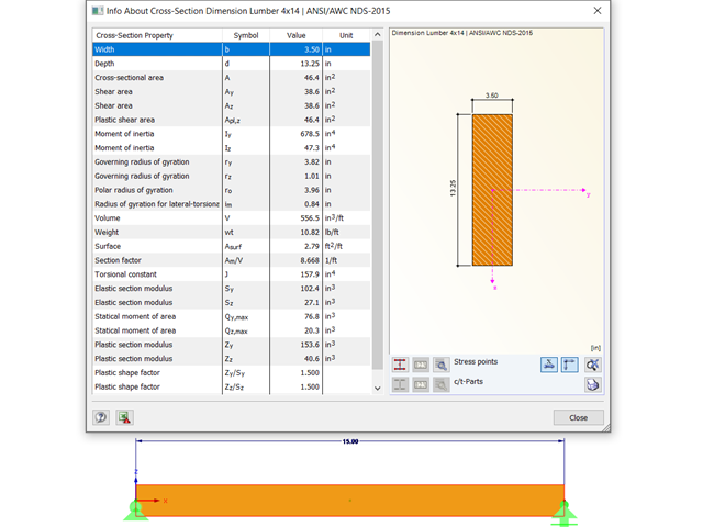
Using the RF-TIMBER AWC module, timber beam design is possible according to the 2018 NDS standard ASD method. Accurately calculating timber member bending capacity and adjustment factors is important for safety considerations and design. The following article will verify the maximum critical buckling in RF-TIMBER AWC using step-by-step analytical equations as per the NDS 2018 standard, including the bending adjustment factors, adjusted bending design value, and final design ratio.
.png?mw=640&hash=6e011ea537587ceb48d9e642d642150a151c551e)
The ASCE 7-16 standard requires both balanced and unbalanced snow load case scenarios for a structure's design consideration. While this may be more intuitive for flat or even gable/hip type roofs, the determination of snow loads is increasingly difficult for arch roofs due to complex geometry. However, with guidance from ASCE 7-16 on snow load calculations for curved roofs and RFEM's efficient load application tools, it is possible to consider both balanced and unbalanced snow loads for a reliable and safe structure design.

The fire resistance design can be performed according to EN 1993-1-2 in RF-/STEEL EC3. The design is carried out according to the simplified calculation method for the ultimate limit state. Claddings with different physical properties can be selected as fire protection measures. You can select the standard temperature-time curve, the external fire curve, and the hydrocarbon curve to determine the gas temperature.
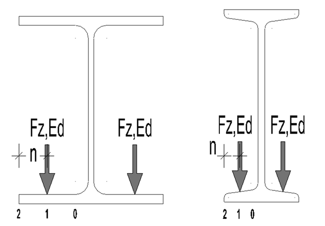
For suspension cranes, the bottom chord of the runway girder is subjected to local flange bending due to the wheel loads in addition to the main load-bearing capacity. The bottom chord behaves like a slab due to these local bending stresses, and has a biaxial stress condition [1].
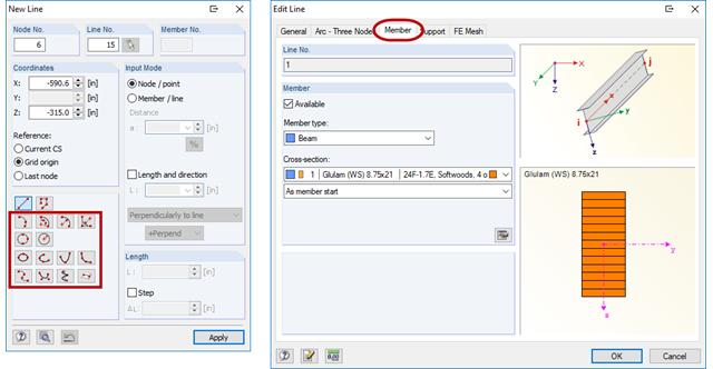
RFEM offers the possibility to model also curved beams. To do this, a curved line must be created first (see Figure 01). This line can then be assigned a beam with a cross-section. The advantages over modeling with beam segments are easier handling during the modeling, as well as a clearer result output of the internal forces.
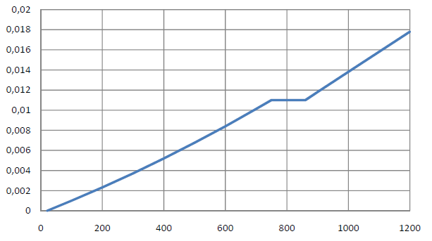
You can apply nominal temperature‑time curves in RFEM or RSTAB using RF‑/STEEL EC3. For this, the standard time-temperature curve (ETK), the external fire curve and the hydrocarbon fire curve are implemented in the program. Based on these temperature curves, the add‑on module can calculate the temperature in the steel cross‑section and thus perform the fire design using the determined temperatures. This article explains the thermal behavior of structural steel, as this has a direct impact on the calculation of component temperatures in RF‑/STEEL EC3.

Cable and tensile membrane structures are regarded as very slender and aesthetic building structures. The partly very complex double-curved shapes can be found using suitable form-finding algorithms. One possible solution is to search for the form via the equilibrium between the surface stress (provided prestress and an additional load such as self-weight, pressure, and so on) and the given boundary conditions.
A single-span beam with lateral and torsional restraint is to be designed according to the recommendations of Eurocode 3 and AISC. If the beam does not reach the required load-bearing capacity, it must be stabilized.

When designing bending-resistant connections from I-beams, the connection is dissolved into the individual parts. For these basic components of a joint, there are separate formula calculators for load-bearing capacity and stiffness. In RFEM and RSTAB, frame joints can be designed using the RF-/FRAME-JOINT Pro add-on module.