48 Results
View Results:
Sort by:

Lateral-Torsional Buckling (LTB) is a phenomenon that occurs when a beam or structural member is subjected to bending and the compression flange is not sufficiently supported laterally. This leads to a combination of lateral displacement and twisting. It is a critical consideration in the design of structural elements, especially in slender beams and girders.

When a concrete slab is set upon the top flange, its effect is like a lateral support (composite construction), preventing problems of torsional buckling stability. If there is a negative distribution of the bending moment, the bottom flange is subjected to compression and the top flange is under tension. If the lateral support given by the stiffness of the web is insufficient, the angle between the bottom flange and the web intersection line is variable in this case so that there is a possibility of distortional buckling for the bottom flange.

This article shows you how to create contacts between two or more parallel surfaces by controlling the transfer of forces between them.

A standard scenario in timber member construction is the ability to connect smaller members by means of bearing on a larger girder member. Additionally, member end conditions may include a similar situation where the beam is bearing on a support type. In either scenario, the beam must be designed to consider the bearing capacity perpendicular to the grain according to NDS 2018 Sec. 3.10.2 and CSA O86:19 Clauses 6.5.6 and 7.5.9. In general structural design software, it is typically not possible to carry out this full design check, as the bearing area is unknown. However, in the new generation RFEM 6 and Timber Design add-on, the added 'design supports' feature now allows users to comply with the NDS and CSA bearing perpendicular to the grain design checks.

In order to create a surface model with failing supports close to reality, an option called "Failure if contact perpendicular to surfaces failed" is available in RFEM 5 for contact solids under "Contact Parallel to Surfaces".

This article deals with rectilinear elements of which the cross-section is subjected to axial compressive force. The purpose of this article is to show how very many parameters defined in the Eurocodes for concrete column calculation are considered in the RFEM 5 structural analysis software.

This article compares the design to the one in the referenced article: Design of Concrete Columns Subjected to Axial Compression with RF-CONCRETE Members. It is, therefore, about taking exactly the same theoretical application carried out in RF-CONCRETE Members and reproducing it in RF-CONCRETE Columns. Thus, the objective is to compare the different input parameters and the results obtained by the two add-on modules for the design of column-like concrete members.

In this article, the adequacy of a 2x4 dimension lumber subject to combined biaxial bending and axial compression is verified using the RF-/TIMBER AWC add-on module. The beam-column properties and loading are based on example E1.8 of AWC Structural Wood Design Examples 2015/2018.

In RFEM, you can display the contact properties between two surfaces by means of contact solids. Among other things, you should ensure that both contact surfaces of a contact solid have the same integrated objects. Therefore, when modeling the contact surfaces, we recommend using the copy function in order to create the second contact surface.

In RFEM, you can display the contact properties between two surfaces by means of contact solids.
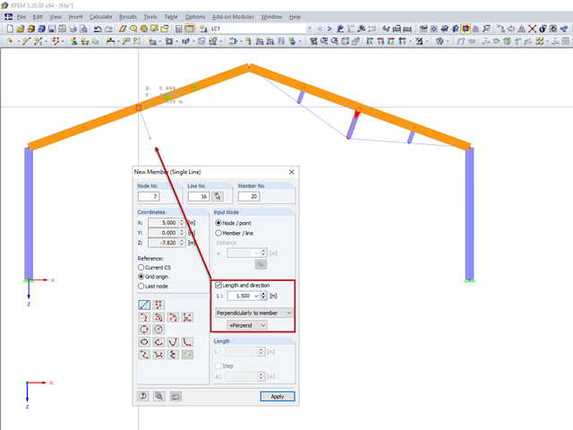
For a frame trussed from below, compression members are to be modelled perpendicular to the inclined beam. The member length and the intersection with the horizontal beam are defined.

Supports contributing to a load reduction only under compression or tension can be defined as nonlinear supports in RFEM and RSTAB. It is not always easy for the user to select the correct nonlinearity for "failure under tension" or "failure under compression".

The German Annex to EN 1992‑1‑1, the National Addition NCI to Article 9.2.1.2 (2), recommends to dispose the tension reinforcement in the flange plate of T‑beam cross‑sections on a maximum of one width corresponding to the half of a computed effective flange width beff,i according to Expression (5,7a).

In EN 1993-1-1, the General Method was introduced as a design format for stability analyses that can be applied to planar systems with arbitrary boundary conditions and variable structural height. The design checks can be performed for loading in the main load-bearing plane and simultaneous compression. The stability cases of lateral-torsional buckling and flexural buckling are analyzed from the main supporting plane; that is, about the weak component axis. Therefore, the issue often arises as to how to design, in this context, flexural buckling in the main load-bearing plane.

If nonlinear effects - such as failing supports, foundations, member nonlinearities, or contact solids - are used in the model, you can deactivate them in the global calculation parameters.
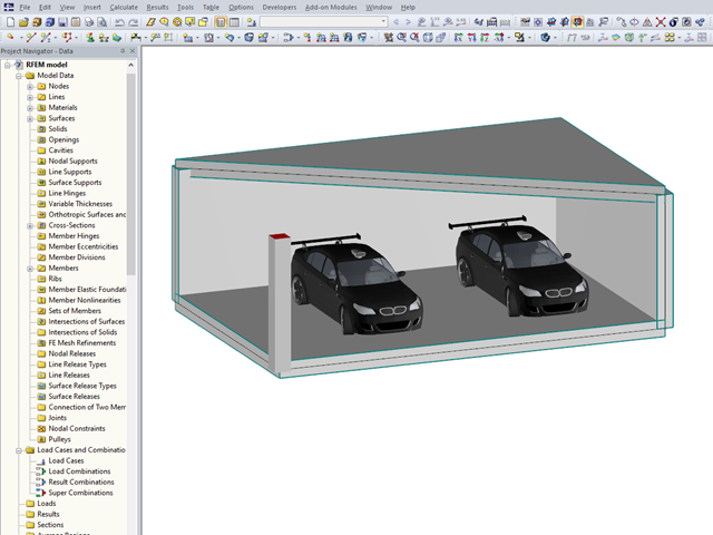
In RFEM 5 and RSTAB 8, you can add visual objects to the model in order to make a convincing impression on your client when presenting the structural model. These objects allow both laypersons and engineers to better understand the dimensions of the system.

The design of cold-rolled steel products is defined in EN 1993-1-3. Typical cross-section shapes are channel, C, Z, top hat, and sigma sections. These are cold-rolled steel products made of thin-walled sheet metal that has been cold-formed by roll-forming or bending methods. When designing the ultimate limit states, it is also necessary to ensure that local transverse forces do not lead to compression, crippling of the web, or local buckling in the web of the sections. These effects can be caused by local transverse forces by the flange into the web, as well as by support forces at the supported points. Section 6.1.7 of EN 1993-1-3 specifies in detail how to determine the resistance of the web Rw,Rd under local transverse forces.

Slender bending beams that have a large h/w ratio and are loaded parallel to the minor axis tend to have stability issues. This is due to the deflection of the compression chord.
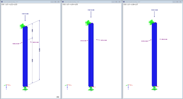
This example will show what you should consider when you perform column design for bending and compression with regard to the internal forces from load combinations and result combinations.
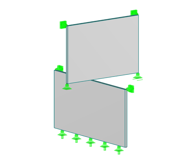
This article describes how to determine the contact force between two objects behaving like walls that are diagonally inclined at a certain angle on top of each other. Define a nodal release to determine this contact force. Since a nodal release requires certain conditions, this article shows two examples.
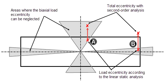
Daily tasks in reinforced concrete design also include designing compression elements subjected to biaxial bending. The following article describes the different methods according to Chapter 5.8.9, EN 1992-1-1, which can be used to design compression elements with biaxial load eccentricities by means of the nominal curvature method according to 5.8.8.
The definition of the non-linear contact problem plays an important role for more detailed investigations of shear/hole bearing connections or their immediate environment. This article uses a solid model to search for comparable and simplified surface models.
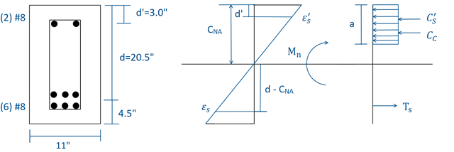
Using RF-CONCRETE Members, concrete beam design is possible according to ACI 318-14. Accurately designing concrete beam tension, compression, and shear reinforcement is important for safety considerations. The following article will confirm the reinforcement design in RF-CONCRETE Members using step-by-step analytical equations as per the ACI 318-14 standard, including moment strength, shear strength, and required reinforcement. The doubly reinforced concrete beam example analyzed includes shear reinforcement and will be designed under the ultimate limit state (ULS) design.
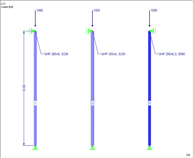
This article is about the stability analysis of a steel column with axial compression according to EN 1993‑1‑1, Clause 6.3.1. Additionally, a variation study is carried out aiming at steel optimization.
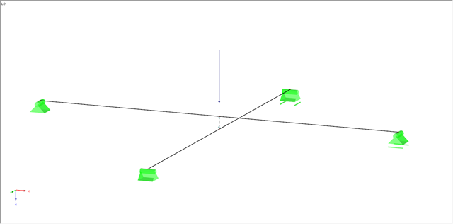
From time to time, two intersecting beams overlap at a short distance. Such a structure raises the question, with regard to the modeling, of how it is possible to consider a contact with force transmission under compression between the two beams, while the contact under tension (for example, in case of a lifting top beam) should fail.
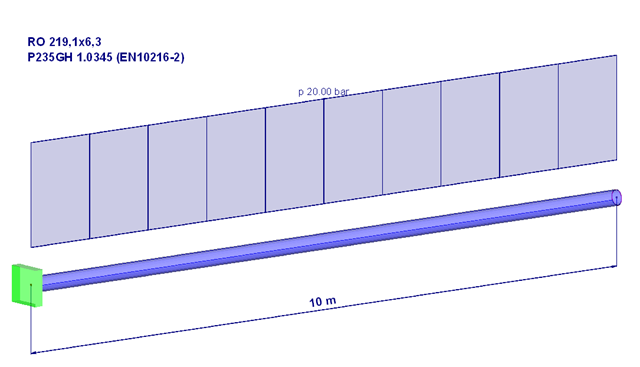
Piping systems are exposed to a variety of loads. One of the most decisive is internal pressure. This article will, therefore, deal with the stresses and deformations resulting from a pure internal compression load in the pipe wall or for the pipe.
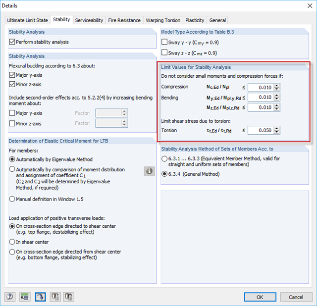
As of the program version X.11, the filter options of small compression forces or moments for stability analysis in RF‑/STEEL EC3 have been revised. The revision of these filter options in the "Stability" tab of the "Details" dialog box allows you to work in the module transparently, since they are now independent of the design.
![Formula Symbols for Connection Between Chords and Web (Source: [1])](/en/webimage/009346/2418256/01-en-3-png.png?mw=640&hash=7a1bc6e87da6f5aeb6d26a130c6ca3dfb6edb8a4)
In order to ensure the effects of panels, which should act as tensile or compression chords, it is necessary to connect them to the web in a shear-resistant manner. This connection is obtained in a similar way as the shear transfer in the joint between concreting sections by using the interaction between compressive struts and ties. In order to ensure the shear resistance, it must be verified that the compressive strut resistance is given and the tie force can be absorbed by the transverse reinforcement.
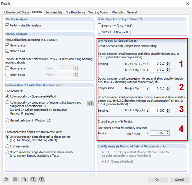
For situations where no design is available, RF-/STEEL EC3 provides the option to neglect the respective internal forces. Examples of such situations are: bending and compression on angle sections, multi-axial bending for the design according to the General Method, torsion.

As an alternative to the equivalent member method, this article describes the possibility to determine the internal forces of a wall at risk of buckling according to the second-order analysis, taking imperfections into account, and to subsequently perform the cross-section design for bending and compression.