63 Results
View Results:
Sort by:

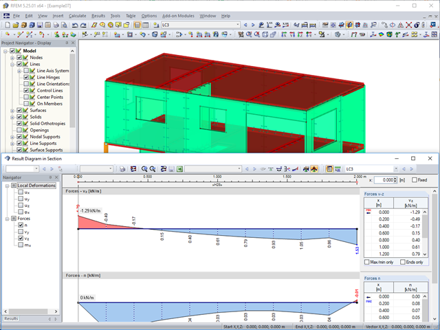
In this article, the calculation of a timber panel wall with the beam panel thickness type is compared with a manual calculation.

Custom sections are often required in cold-formed steel design. In RFEM 6, the custom section can be created using one of the “Thin-Walled” sections available in the library. For other sections that do not meet any of the 14 available cold-formed shapes, the sections can be created and imported from the standalone program, RSECTION. For general information on AISI steel design in RFEM 6, refer to the Knowledge Base article provided at the end of the page.

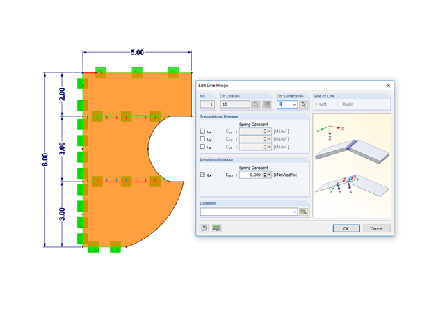
The properties of the connection between a reinforced concrete slab and a masonry wall can be correctly considered in the modeling using a special line hinge that is available in RFEM 6. This article will show you how to define this type of hinge using a practical example.

The optimal scenario in which punching shear design according to ACI 318-19 [1] or CSA A23.3:19 [2] should be utilized is when a slab is experiencing a high concentration of loading or reaction forces occurring at one single node. In RFEM 6, the node in which punching shear is an issue is referred to as a punching shear node. The causes of these high concentration of forces can be introduced by a column, concentrated force, or nodal support. Connecting walls can also cause these concentrated loads at wall ends, corners, and ends of line loads and supports.

The stand-alone program RSECTION is at your disposal for determining section properties and performing stress analysis for thin-walled and massive cross-sections. The program can be connected to both RFEM and RSTAB so that sections from RSECTION are also available in the RFEM and RSTAB library. Likewise, internal forces from RFEM and RSTAB can be imported into RSECTION.

You can use the stand-alone program RSECTION to determine the section properties for any thin-walled and massive cross-sections, as well as to perform a stress analysis. The previous Knowledge Base article titled "Graphical/Tabular Creation of User-defined Cross-sections in RSECTION 1" discussed the basis of defining cross-sections in the program. This article, on the other hand, is a summary of how to determine the section properties and perform a stress analysis.

RSECTION 1 is a stand-alone program for determining section properties for both thin-walled and massive cross-sections, as well as for performing a stress analysis. In addition, the program can be connected to both RFEM and RSTAB: sections from RSECTION are available in the RFEM/RSTAB libraries, and internal forces from RFEM/RSTAB can be imported into RSECTION.

In RFEM 6, seismic analysis can be done by using the Modal Analysis and the Response Spectrum Analysis add-ons. Once the spectral analysis has been performed, it is possible to use the Building Model add-on to display story actions, interstory drifts, and forces in shear walls.

In accordance with Sect. 6.6.3.1.1 and Clause 10.14.1.2 of ACI 318-19 and CSA A23.3-19, respectively, RFEM effectively takes into consideration concrete member and surface stiffness reduction for various element types. Available selection types include cracked and uncracked walls, flat plates and slabs, beams, and columns. The multiplier factors available within the program are taken directly from Table 6.6.3.1.1(a) and Table 10.14.1.2.

The punching shear design, in line with EN 1992-1-1, should be performed for slabs with a concentrated load or reaction. The node where the design of punching shear resistance is performed (that is, where there is a punching problem) is called a node of punching shear. The concentrated load at these nodes can be introduced by columns, concentrated force, or nodal supports. The end of the linear load introduction on slabs is also regarded as a concentrated load and therefore, the shear resistance at wall ends, wall corners, and ends or corners of line loads and line supports should be controlled as well.

General thin-walled cross-sections often have asymmetrical geometries. The principal axes of such sections are then not parallel to the horizontally and vertically aligned axes Y and Z. When determining the cross-section properties, the angle α between the center-of-gravity axis y and the principal axis u is determined in addition to the principal axis-related moments of inertia.

The SHAPE‑THIN and SHAPE‑MASSIVE cross-section programs are suitable for determining the cross-section properties of common thin-walled or thick-walled sections. These cross-section properties are also available for further analyses in RSTAB and RFEM.

In the case of wall-like load-bearing behavior of the cross-laminated timber plate, special attention must be paid to the shear deformation in the plane of the pane and thus, in particular, to the displaceability of the fasteners.

The support of the cross-laminated timber panel deserves special attention. Usually, a cross‑laminated wall is secured against shearing by means of shear connectors and against lifting forces by means of tie rods.
One of the advantages of entering the structure in RFEM is the complete freedom when selecting the geometry. You can easily select a structure where re‑entrant rolling corners are given as shown in the image.

With the SHAPE‑THIN cross‑section properties software, you can create any thin‑walled cross‑section and use it in RFEM or RSTAB as a member cross‑section. SHAPE‑THIN can give all relevant cross‑section values of any cross‑section for a design and stress analysis.

DXF layers of ground plans cannot be used directly in FEA programs because only the outer contours of the elements (walls, ceilings, and so on) are available in the drawing. The FEM programs require system axes, but only the outer contours of the elements (walls, ceilings, and so on) are available in the DXF drawing.

The new "Result Beam" member type in RFEM 5 allows you to determine the load sums of individual floors easily. To do this, model a member in the relevant floor or in all floors, then specify the relevant walls as inclusive objects in the parameters of the result beam. RFEM then integrates the surface internal forces into member internal forces.
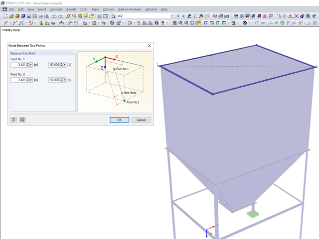
Until now, if you wanted to determine the centroid of a rectangle, it was necessary to define a line from one corner point to the diagonally opposite point. You obtained the centroid by dividing this line. In RFEM 5 and RSTAB 8, you now have the possibility to create a node between two points. Thus, it is sufficient to select the corner points; then you can determine the distance in absolute or relative values.
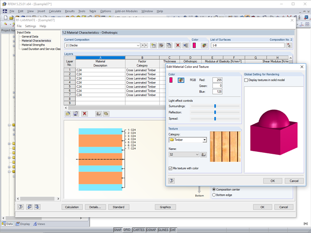
To better distinguish between the different layer compositions (for example, for walls and ceilings), you can assign user‑defined colors and textures to each composition.
In this article, we will look at the design of shear connectors of cross‑laminated timber structures that transfer the longitudinal forces of the shear wall to the soil.
A fluid with a constant density in a homogeneous gravity field exerts a hydrostatic pressure on its comprehensive container wall according to Pascal's law.

Concrete on its own is characterized by its compressive strength. An important part of reinforced concrete is reinforcing steel, which contributes to both the compressive and the tension resistance of the concrete. Welded wire fabric is generally located in the tension areas of the beams or surface elements (hollow core ceiling, wall, shell) to transfer the tensile forces induced by external loading.

According to Book 631 of the DAfStb (German Committee for Structural Concrete), Chapter 2.4, the structural behavior of ceilings changes if their continuous support by walls is interrupted in areas of openings. Depending on the length of the opening area and the plate thickness, measures are necessary regarding the analysis of the ceiling in the area of the opening.

If a rib is part of a nonlinear design or is rigidly connected to following walls, a surface should be used for the modeling instead of a member. So that the rib can still be designed as a member, a result member with the correct eccentricity is required, which transforms the surface internal forces into member internal forces.
This article describes the design of timber panel walls due to generated horizontal loads.

Reinforced concrete surface design for slabs, plates, and walls is possible in the RF-CONCRETE Surfaces module according to the ACI 318-19 or the CSA A23.3-19 standard. A common approach for slab design is the use of design strips for determining the average one-way internal forces over the width of the strip. This design strip method essentially takes a two-way slab element and applies a simpler one-way approach to determine the required reinforcement needed along the strip length.
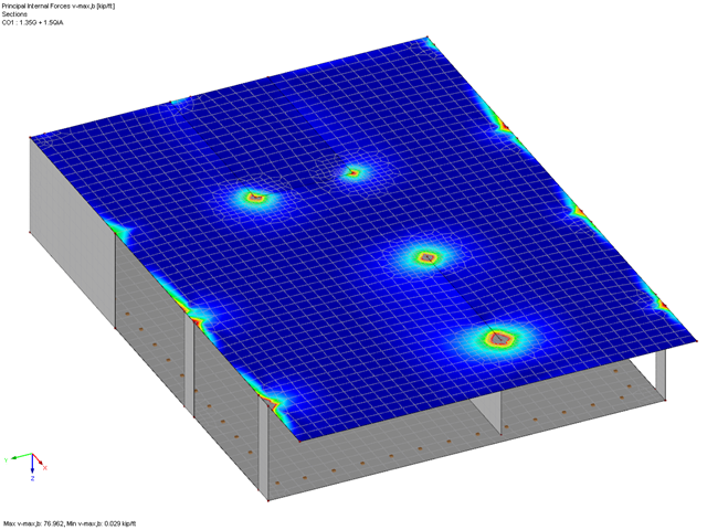
In RF-PUNCH Pro, you can perform the punching shear design on wall corners and wall ends. The basis for the design is the punching load, which is automatically determined from the RFEM internal forces in the connected surface. Since the surface internal forces from the RFEM calculation may be subject to the influence of singularity locations, this can also have a negative influence on the determined punching load at the wall corner or end. This article describes possible optimization options that you can use to minimize this unfavorable influence.

The design of cold-rolled steel products is defined in EN 1993-1-3. Typical cross-section shapes are channel, C, Z, top hat, and sigma sections. These are cold-rolled steel products made of thin-walled sheet metal that has been cold-formed by roll-forming or bending methods. When designing the ultimate limit states, it is also necessary to ensure that local transverse forces do not lead to compression, crippling of the web, or local buckling in the web of the sections. These effects can be caused by local transverse forces by the flange into the web, as well as by support forces at the supported points. Section 6.1.7 of EN 1993-1-3 specifies in detail how to determine the resistance of the web Rw,Rd under local transverse forces.

Utilize the RF-/STEEL Cold-Formed Sections module extension to perform ultimate limit state designs of cold-formed sections according to EN 1993-1-3 and EN 1993-1-5. In addition to the cold-formed cross-sections from the cross-section database, you can design general cross-sections from SHAPE-THIN.