De nombreux composants incluent des plaques insérées, par exemple une platine d’about, une nervure, une plaque de connexion, etc. Vous pouvez également insérer une plaque comme composant distinct, par exemple en tant que platine en tête d’un poteau, comme renfort d’une section ouverte ou comme gousset, où vous connectez une pièce avec la composante plaque de connexion. L’illustration ci-dessous montre une platine en tête et un gousset.
Élément
Dans la première catégorie des paramètres de composant, les dimensions de la plaque et son matériau doivent être définis. Vous pouvez sélectionner parmi les matériaux existants ou définir un nouveau matériau. Outre une forme rectangulaire ou ronde, la définition d’une forme polygonale est également disponible. Si vous souhaitez spécifier cette dernière, vous pouvez indiquer les points de définition correspondants du polygone dans Points du polygone.
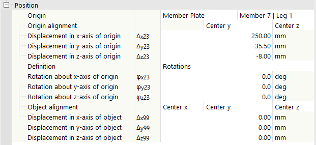
Position
Le positionnement de la plaque dans l’assemblage est contrôlé par cette prochaine catégorie.
Origine
Sélectionnez le composant Origine, auquel les déplacements et les rotations de la plaque se réfèrent.
Le réglage par défaut est Assemblage, c’est-à-dire l’origine de toute l’assemblage. Vous pouvez également choisir une barre, une plaque de barre, une autre plaque, un plan auxiliaire ou un solide auxiliaire comme composant de référence. Basé sur le système de coordonnées de ce composant, vous pouvez déplacer et pivoter la plaque pour ajuster leur agencement.
Alignement de l’origine
Cette option est disponible lorsqu’une pièce est définie comme origine. Vous pouvez sélectionner un point de référence de la pièce où la plaque doit être fixée.
Il y a trois listes (deux pour les barres) pour les coordonnées spatiales pertinentes, chacune avec trois options.
| Milieu | Le milieu de la plaque se réfère au centre de gravité de la pièce de référence. |
| Le milieu de la plaque se réfère à la face positive (cadre de contour) de la pièce de référence. | |
| - | Le milieu de la plaque se réfère à la face négative (cadre de contour) de la pièce de référence. |
De plus, la position de la plaque peut également être ajustée selon des déplacements absolus et des rotations par rapport à l’objet de référence. Cela se fait par les entrées correspondantes dans les lignes sous l’alignement relatif de l’origine.
Alignement de l’objet
Ici, vous pouvez choisir le point de référence de la plaque utilisée pour l’assemblage. Il n’est pas obligatoire qu’il soit attaché au centre de gravité à l’origine.
Il y a encore une fois trois listes avec trois options chacune.
| Milieu | La plaque elle-même est alignée avec sa ligne médiane. |
| La plaque elle-même est alignée avec sa face positive (cadre de contour) dans la direction des coordonnées respectives. | |
| - | La plaque elle-même est alignée avec sa face négative (cadre de contour) dans la direction des coordonnées respectives. |
Avec les options d’entrée supplémentaires, la plaque peut être déplacée dans son orientation pivotée (par rapport à l’origine).


