27 Wyniki
Wyświetl wyniki:
Sortuj według:

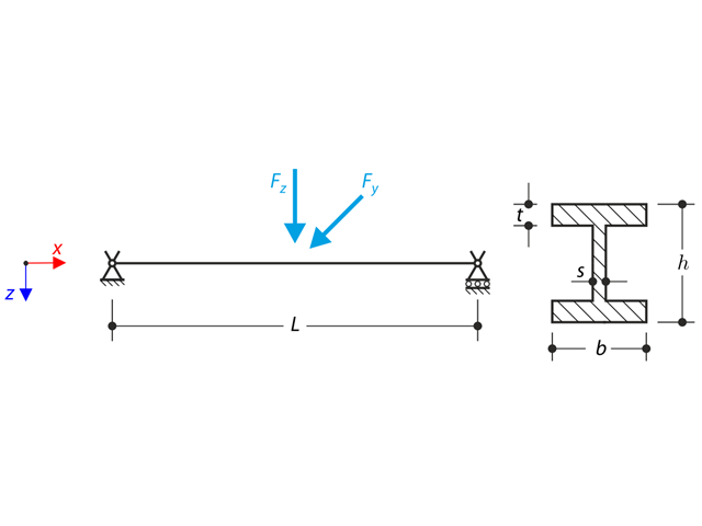
Konstrukcja składa się z swobodnie podpartej belki o przekroju dwuteowym. Obrót osiowy φx jest ograniczony na obu końcach, ale przekrój może ulec deplanacji (podpora widełkowa). Belka posiada początkową imperfekcję w kierunku Y zdefiniowaną jako krzywa paraboliczna o maksymalnym przemieszczeniu 30 mm w środku. Obciążenie równomierne zostaje przyłożone w środku górnego pasa profilu dwuteowego. Problem opisano za pomocą poniższego zestawu parametrów. Przykład obliczeniowy oparty jest na przykładzie wprowadzonym przez Gensichen i Lumpe.

Konstrukcja składa się z belki o przekroju dwuteowym i dwóch kratownic rurowych. The structure contains several imperfections and it is loaded by the force Fz. Ciężar własny jest pomijany w tym przykładzie. Determine the deflections uy and uz and axial rotation φx at the endpoint (Point 4). Przykład obliczeniowy oparty jest na przykładzie wprowadzonym przez Gensichen i Lumpe.
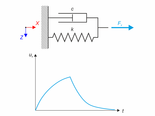
Model materiałowy Kelvina-Voigta składa się z równolegle połączonych sprężyny liniowej i amortyzatora wiskotycznego. W tym przykładzie weryfikacyjnym sprawdzane jest zachowanie tego modelu w czasie przy obciążeniu i relaksacji w przedziale czasowym 24 godzin. Stała siła Fx jest stosowana przez 12 godzin, a pozostałe 12 godzin to model materiałowy bez obciążenia (relaks). Oceniane jest odkształcenie po 12 i 20 godzinach. Wykorzystano analizę historii czasowej metodą liniową niejawną metodą Newmarka.
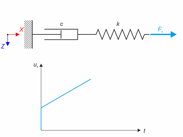
Model materiałowy Maxwell składa się z szeregowo połączonych sprężyny liniowej i amortyzatora wiskotycznego. W tym przykładzie weryfikacyjnym sprawdzane jest zachowanie się modelu w czasie. Model materiałowy Maxwella jest obciążony stałą siłą Fx. Siła ta powoduje początkowe odkształcenie sprężyny, a następnie odkształcenie narasta w czasie dzięki tłumikowi. Odkształcenie jest obserwowane w momencie obciążenia (20 s) i na końcu analizy (120 s). Wykorzystano analizę historii czasowej metodą liniową niejawną metodą Newmarka.
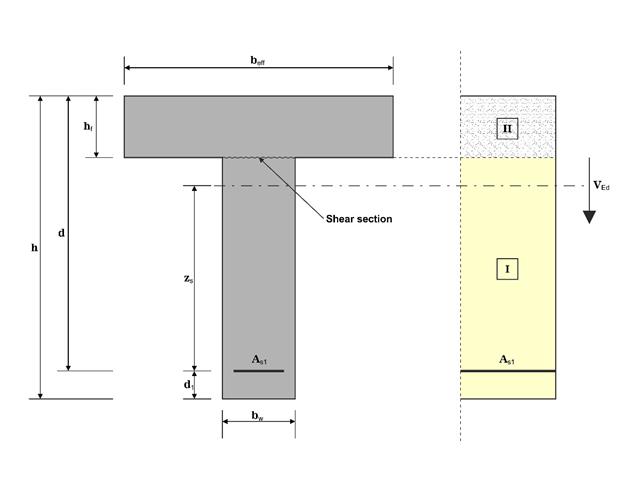
W tym przykładzie ścinanie na granicy między betonem wylanym w różnym czasie a odpowiednim zbrojeniem jest określane zgodnie z DIN EN 1992-1-1. Wyniki uzyskane w programie RFEM 6 zostaną porównane z poniższymi obliczeniami ręcznymi.
Obrót osiowy profilu dwuteowego jest ograniczony na obu końcach za pomocą podpór widełkowych (nieograniczona deplanacja). W środku konstrukcja jest obciążona dwiema siłami poprzecznymi. Ciężar własny jest pomijany w tym przykładzie. Określ maksymalne ugięcia konstrukcji uy,max i uz,max, maksymalny obrót φx,max, maksymalne momenty zginające My,max i Mz,max i maksymalne momenty skręcające MT,max, MTpri,max, MTsec,max i Mω,max. Przykład obliczeniowy oparty jest na przykładzie wprowadzonym przez Gensichen i Lumpe.
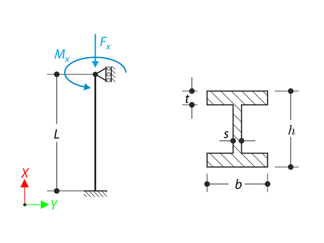
Pręt o zadanych warunkach brzegowych jest obciążony momentem skręcającym i siłą osiową. Pomijając ciężar własny, należy określić maksymalne odkształcenie skręcające belki' oraz jej wewnętrzny moment skręcający, zdefiniowany jako suma głównego momentu skręcającego i skręcającego wywołanego siłą normalną. Należy porównać te wartości, przyjmując lub pomijając wpływ siły normalnej. Przykład obliczeniowy oparty jest na przykładzie wprowadzonym przez Gensichen i Lumpe.
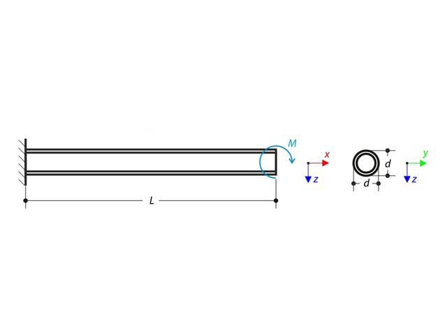
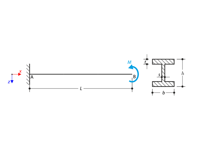
Wspornik jest obciążony momentem na jego wolnym końcu. Korzystając z analizy geometrycznej liniowej i analizy dużych deformacji oraz pomijając ciężar własny belki, należy określić maksymalne ugięcia na swobodnym końcu. Przykład obliczeniowy oparty jest na przykładzie wprowadzonym przez Gensichen i Lumpe.
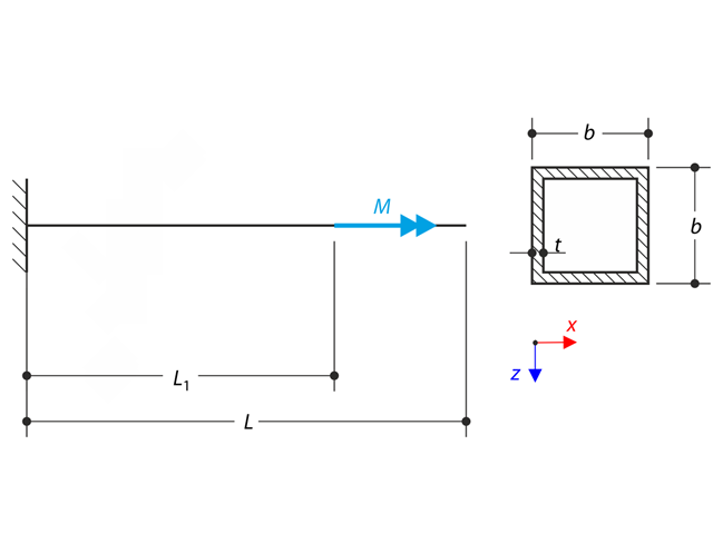
Cienkościenny wspornik profilu QRO jest w pełni zamocowany na lewym końcu, a deplanacja jest wolna. Wspornik jest poddany skręcaniu. Uwzględniane są niewielkie odkształcenia, a ciężar własny jest pomijany. Określ maksymalny obrót, moment główny, moment drugorzędny i moment deplanacyjny. Przykład obliczeniowy oparty jest na przykładzie wprowadzonym przez Gensichen i Lumpe.
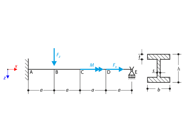
Belka jest w pełni utwierdzona (skrętność jest ograniczona) na lewym końcu i podparta na podporze widełkowej (swobodna deplanacja) na prawym końcu. Belka jest poddawana działaniu momentu obrotowego, siły podłużnej i siły poprzecznej. Zdefiniuj zachowanie głównego momentu skręcającego, drugorzędnego momentu skręcającego i momentu skrępowanego. Przykład obliczeniowy oparty jest na przykładzie opracowanym przez Gensichen i Lumpe (patrz odniesienie).
Wspornik o profilu dwuteowym jest podparty na lewym końcu i jest obciążony momentem obrotowym M. Celem tego przykładu jest porównanie podpory nieruchomej z podporą widełkową i zbadanie zachowania się niektórych reprezentatywnych wielkości. Przeprowadzane jest również porównanie z rozwiązaniem za pomocą płyt. Przykład obliczeniowy oparty jest na przykładzie wprowadzonym przez Gensichen i Lumpe.
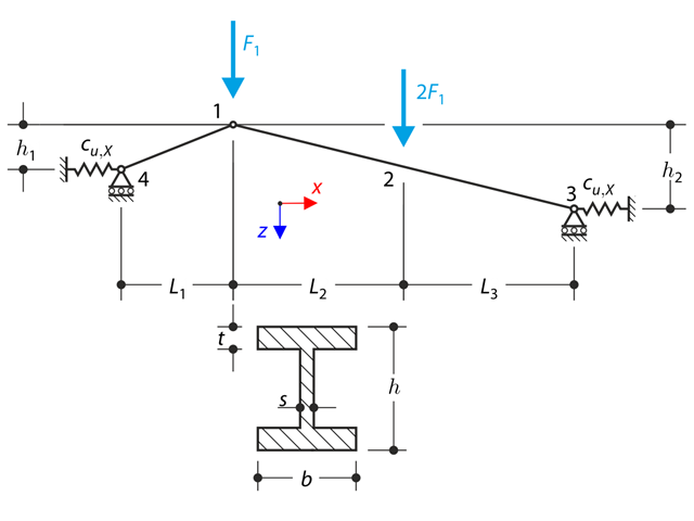
Konstrukcja wykonana z kratownic o profilu dwuteowym jest podparta na obu końcach przez sprężyste podpory ślizgowe i obciążona siłami poprzecznymi. W tym przykładzie pominięto ciężar własny . Należy określić ugięcie konstrukcji, moment zginający, siłę normalną w danych punktach testowych oraz ugięcie poziome podpory sprężystej.
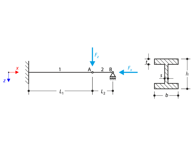
Konstrukcja z profilu I jest w pełni utwierdzona na lewym końcu i osadzona w podporze przesuwnej na prawym końcu. Konstrukcja składa się z dwóch segmentów. Ciężar własny jest pomijany w tym przykładzie. Określ maksymalne ugięcie konstrukcji uz,max, moment zginający My na nieruchomym końcu, obrót &2,y segmentu 2 oraz siły reakcji RBz za pomocą analizy geometrycznie liniowej i analizy drugiego rzędu. Przykład obliczeniowy oparty jest na przykładzie wprowadzonym przez Gensichen i Lumpe.
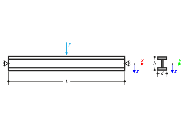
Belka podparta przegubowo na obu końcach jest obciążona siłą poprzeczną w środku. Pomijając ciężar własny i sztywność na ścinanie, należy określić maksymalne ugięcie, siłę normalną i moment w środku rozpiętości, przyjmując teorię drugiego i trzeciego rzędu. Przykład obliczeniowy oparty jest na przykładzie opracowanym przez Gensichen i Lumpe (patrz odnośnik).
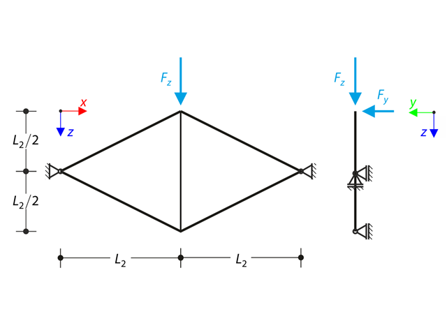
Płaska kratownica składająca się z czterech nachylonych prętów i jednego pręta pionowego jest obciążona w górnym węźle siłą pionową Fz oraz siłą Fy leżącą poza płaszczyzną. Zakładając analizę dużych deformacji i pomijając ciężar własny, należy określić siły normalne prętów oraz przemieszczenie górnego węzła z płaszczyzny uy. Przykład obliczeniowy oparty jest na przykładzie wprowadzonym przez Gensichen i Lumpe.
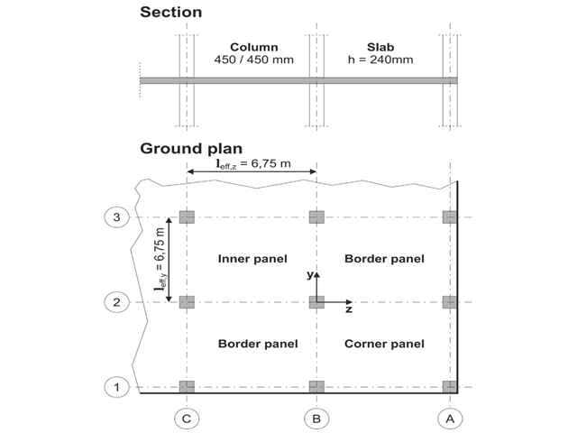
Model oparty jest na przykładzie 4 z [1]: Płyta podparta punktowo.
Należy zaprojektować płaską płytę budynku biurowego o wrażliwych na zarysowania ścianach lekkich. Należy zbadać panele wewnętrzne, brzegowe i narożne. Słupy i płyta są połączone monolitycznie. Słupy skrajne i narożne są zlicowane z krawędzią płyty. Osie słupów tworzą siatkę kwadratową. Jest to układ sztywny (budynek usztywniony ścianami usztywniającymi).
Budynek biurowy ma 5 kondygnacji i ma wysokość 3.000 m. Warunki środowiskowe, które należy przyjąć, określane są jako „zamknięte przestrzenie wewnętrzne”. Występują głównie oddziaływania statyczne.
Celem tego przykładu jest określenie momentów w płycie i wymaganego zbrojenia nad słupami przy pełnym obciążeniu.
Das Architectural Institute of Japan (AIJ) oferuje analizę porównawczą dla symulacji wiatru.
Der Nachfolgende Beitrag dreht sich dabei um den "Przypadek A - wieżowiec w kształcie 2:1:1".
Im Folgenden wird das beschriebene Szenario in RWIND2 unchgebildet und die Ergebnisse mit den den simulierten und der expertellen Resultate des AIJ verglichen.
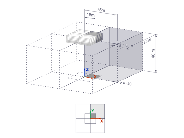
Osiadania sztywnego fundamentu kwadratowego na glinie jeziornej [1] są obliczane w programie RFEM. Modelowana jest jedna czwarta fundamentu. Fundament ma szerokość 75,0 m po obu stronach. Do wygenerowania wyników wykorzystywane są etapy budowy.
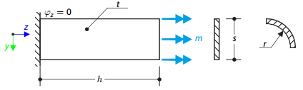
Z jednej strony zamocowana jest cienka płyta, z drugiej strony obciążona momentem rozłożonym. Najpierw płyta jest modelowana jako płaska. Ponadto płyta jest modelowana jako jedna czwarta powierzchni walca. Szerokość modelu płaskiego jest równa długości jednej czwartej obwodu zakrzywionego modelu. Model zakrzywiony ma zatem niemal równą współczynnikowi skręcania model płaski.
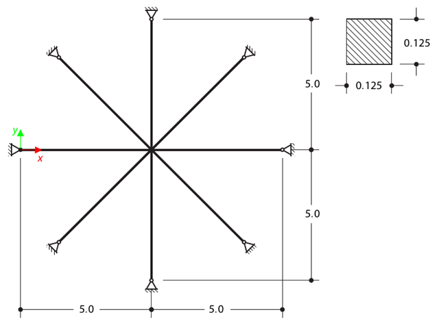
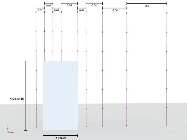
Wyznacz pierwszych szesnaście częstotliwości drgań własnych przekroju podwójnego o przekroju kwadratowym. Każde z ośmiu ramion jest modelowane za pomocą czterech elementów belkowych i posiada na końcu podporę sworzniową (ugięcia w osi x i y są ograniczone). Drgania są uwzględniane tylko w płaszczyźnie xy. Problem jest zdefiniowany zgodnie z normą NAFEMS Benchmarks.

Cienka płyta jest całkowicie zamocowana na lewym końcu i obciążona równomiernym naciskiem na górną powierzchnię. Określ maksymalne ugięcie. Celem tego przykładu jest pokazanie, że powierzchnia o typie sztywności powierzchniowej Bez rozciągania membranowego zachowuje się liniowo przy zginaniu.
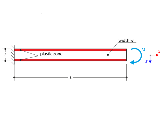
Wspornik jest w pełni zamocowany na lewym końcu i poddany działaniu momentu zginającego z uwzględnieniem plastyczności.
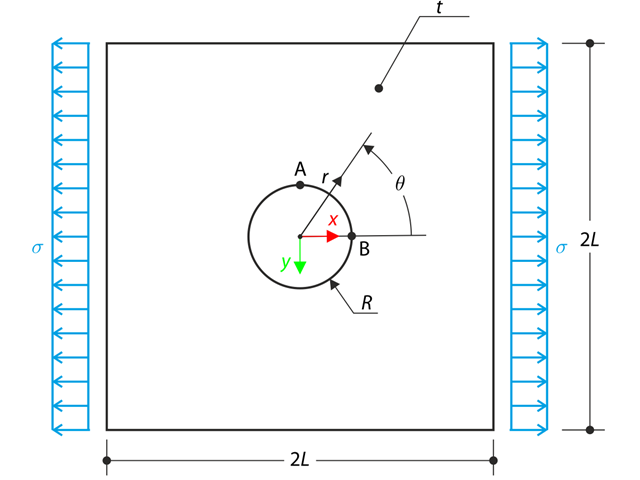
Szeroka płyta z otworem jest obciążona w jednym kierunku naprężeniem rozciągającym σ. Szerokość płyty jest duża w stosunku do promienia otworu i bardzo cienka, biorąc pod uwagę stan naprężenia w płaszczyźnie. Wyznacz naprężenie promieniowe σr, naprężenie styczne σθ i naprężenie styczne τrθ wokół otworu.

Płyta kompaktowa (CD) obraca się z prędkością 10 000 obr./min. Dlatego jest poddawany działaniu siły odśrodkowej. Problem jest zamodelowany jako ćwiartka. Należy określić naprężenie styczne σt na średnicy wewnętrznej i zewnętrznej oraz ugięcie promieniowe ur promienia zewnętrznego.
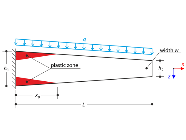
Zbieżny wspornik jest w pełni zamocowany na lewym końcu i poddawany obciążeniu ciągłemu q. W tym przykładzie brane są pod uwagę małe deformacje, a ciężar własny jest pomijany. Określ maksymalne ugięcie.
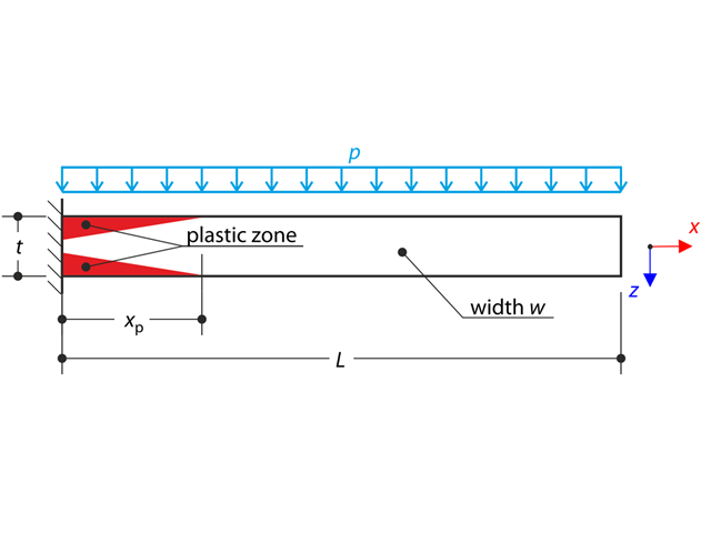
Cienka płyta jest całkowicie zamocowana na lewym końcu i poddana równomiernemu naciskowi. Pod wpływem równomiernego nacisku płyta jest wprowadzana w stan sprężysto-plastyczny.

Modelowana jest powłoka dachu pod obciążeniem ściskającym, w której proste krawędzie są swobodne, a na krawędziach zakrzywionych przesunięcia y i z są ograniczone. Neglecting self‑weight, compute the maximum (absolute) vertical deflection, and compare the results with COMSOL Multiphysics 4.3.