115 Wyniki
Wyświetl wyniki:
Sortuj według:

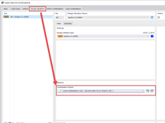
Ocena przemieszczenia kondygnacji w budynku jest kluczowa dla zapewnienia zadowalających parametrów konstrukcyjnych poprzez ograniczenie przemieszczenia kondygnacji. Nadmierne znoszenie może powodować niestateczność systemu i powodować uszkodzenia elementów niekonstrukcyjnych, takich jak ściany działowe. W tym artykule opisano procedurę wyznaczania przemieszczeń międzykondygnacyjnych zgodnie z ASCE 7-22 i rozszerzeniem Model budynku w programie RFEM 6.
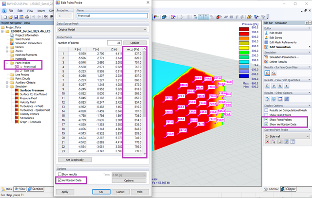
Za pomocą programów RWIND 2 i RFEM 6 można teraz obliczać obciążenia wiatrem na podstawie zmierzonego eksperymentalnie ciśnienia wiatru na powierzchnie. Zasadniczo dostępne są dwie metody interpolacji, umożliwiające rozłożenie ciśnienia mierzonego w izolowanych punktach na powierzchnie. Żądany rozkład ciśnienia można uzyskać za pomocą odpowiedniej metody i ustawień parametrów.
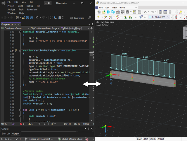
Nasza usługa sieciowa oferuje użytkownikom możliwość komunikacji z programami RFEM 6 i RSTAB 9 za pomocą różnych języków programowania. Funkcje wysokiego poziomu (HLF) firmy Dlubal umożliwiają rozszerzenie i uproszczenie funkcjonalności WebService. Zgodnie z RFEM 6 i RSTAB 9, korzystanie z naszego webservice sprawia, że praca inżyniera jest łatwiejsza i szybsza. Wypróbuj teraz! Ten samouczek pokazuje, jak korzystać z biblioteki C #na prostym przykładzie.
Celem zastosowania programów RFEM 6 i Blender z rozszerzeniem Bullet Constraints Builder jest uzyskanie graficznej reprezentacji zawalenia się modelu na podstawie rzeczywistych danych dotyczących właściwości fizycznych. Program RFEM 6 służy jako źródło geometrii i danych do symulacji. Jest to kolejny przykład, dlaczego ważne jest, aby nasze programy utrzymywać jako tak zwane BIM Open, aby umożliwić współpracę między różnymi dziedzinami oprogramowania.
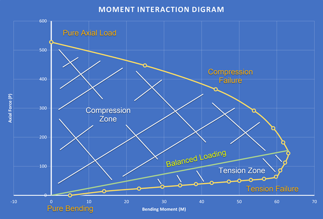
Nowością w programie RFEM 6 podczas wymiarowania słupów betonowych jest możliwość generowania wykresu interakcji momentów zgodnie z ACI 318-19 [1]. Podczas wymiarowania prętów żelbetowych istotnym narzędziem jest wykres interakcji momentów. Wykres interakcji momentów przedstawia zależność między momentem zginającym a siłą osiową w dowolnym punkcie zbrojenia. Cenne informacje, takie jak wytrzymałość i zachowanie betonu w różnych warunkach obciążenia, wyświetlane są wizualnie.
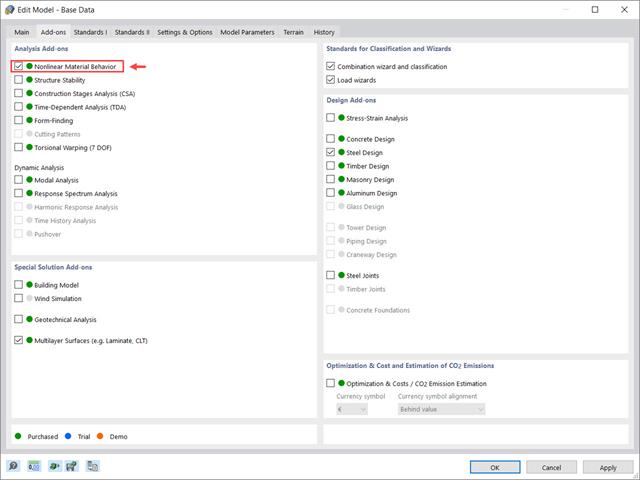
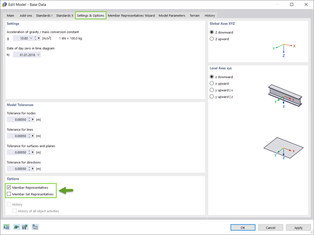
Rozszerzenie Nieliniowe zachowanie materiału umożliwia uwzględnienie nieliniowości materiałowych w programie RFEM 6. Ten artykuł zawiera przegląd dostępnych nieliniowych modeli materiałowych, które są dostępne po aktywowaniu tego rozszerzenia w danych bazowych modelu.
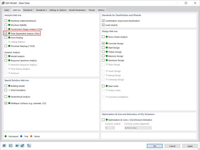
W tym artykule pokazano, w jaki sposób rozszerzenie „Analiza zależna od czasu” jest zintegrowane w programach RFEM 6 i RSTAB 9. Opisuje sposób definiowania danych wejściowych, takich jak charakterystyka materiału zależna od czasu, sposób określania typu analizy i czasy obciążenia.
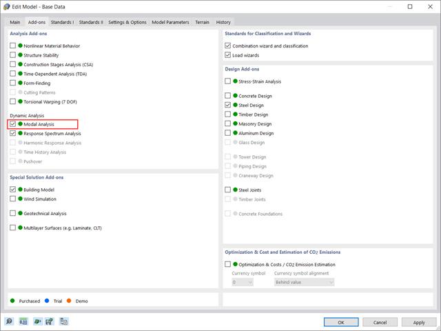
Rozszerzenie „Analiza modalna” w RFEM 6 umożliwia przeprowadzanie analizy modalnej układów konstrukcyjnych, określając w ten sposób wartości drgań własnych, takie jak częstotliwości drgań własnych, kształty modalne, masy modalne i efektywne modalne współczynniki masy. Wyniki te można wykorzystać do obliczeń drgań, a także do dalszych analiz dynamicznych (na przykład obciążenia widmem odpowiedzi).
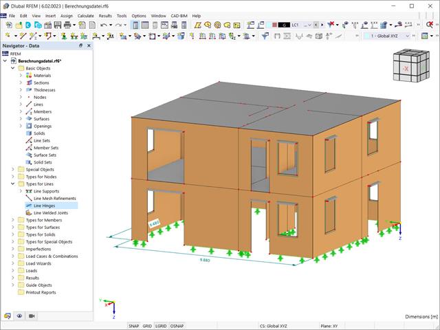
Przy użyciu specjalnego przegubu liniowego dostępnego w programie RFEM 6 można poprawnie uwzględnić podczas modelowania właściwości połączenia płyty żelbetowej ze ścianą murowaną. Z tego artykułu dowiesz się, jak zdefiniować ten typ przegubu na praktycznym przykładzie.
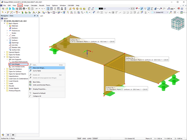
W tym artykule pokażemy, jak prawidłowo uwzględnić połączenie między powierzchniami stykającymi się na jednej linii za pomocą przegubów liniowych w programie RFEM 6.
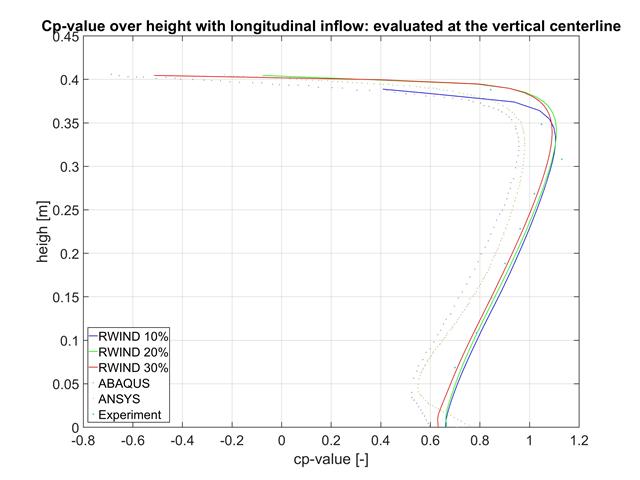
W tym artykule porównujemy wyniki z programów RWIND, ABAQUS i ANSYS z badaniem w tunelu aerodynamicznym przy użyciu prostego geometrycznie modelu.
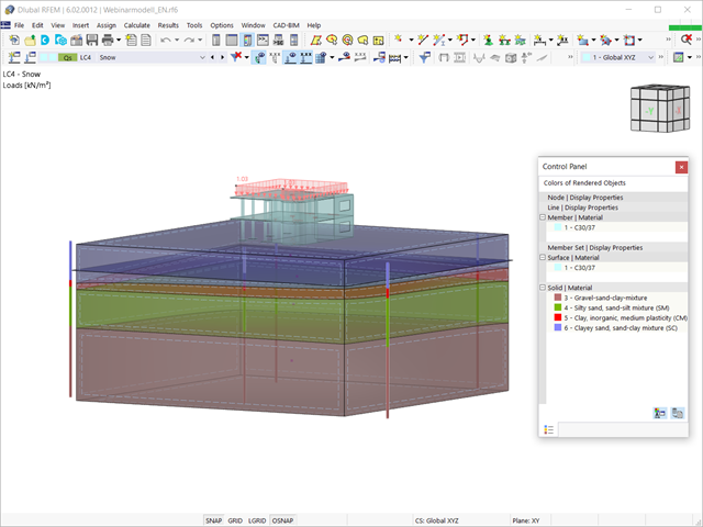
Biorąc pod uwagę, że realistyczne określenie warunków gruntowych znacząco wpływa na jakość analizy statyczno-wytrzymałościowej budynków, w programie RFEM 6 dostępne jest rozszerzenie Analiza geotechniczna, które umożliwia określenie konturu glebowego do analizy.
Sposób udostępnienia danych uzyskanych z badań polowych w rozszerzeniu i wykorzystania właściwości z próbek gruntu do określenia masywów gruntu, które mają być przedmiotem zainteresowania, został omówiony w artykule z Bazy informacji „Tworzenie bryły gruntowej na podstawie próbek gruntu w programie RFEM 6”. W tym artykule omówiono natomiast procedurę obliczania osiadań i parcia gruntu dla budynku żelbetowego.
Sposób udostępnienia danych uzyskanych z badań polowych w rozszerzeniu i wykorzystania właściwości z próbek gruntu do określenia masywów gruntu, które mają być przedmiotem zainteresowania, został omówiony w artykule z Bazy informacji „Tworzenie bryły gruntowej na podstawie próbek gruntu w programie RFEM 6”. W tym artykule omówiono natomiast procedurę obliczania osiadań i parcia gruntu dla budynku żelbetowego.

Analiza modalna jest punktem wyjścia do analizy dynamicznej układów konstrukcyjnych. Można ją wykorzystać do określenia wartości drgań własnych, takich jak częstotliwości drgań własnych, kształty drgań własnych, masy modalne i efektywne współczynniki masy modalnej. Wynik ten może zostać wykorzystany do obliczeń drgań oraz do dalszych analiz dynamicznych (na przykład obciążenia widmem odpowiedzi).

Rozszerzenie Wymiarowanie betonu umożliwia wymiarowanie słupów betonowych zgodnie z ACI 318-19. Poniższy artykuł potwierdzi wymiarowanie zbrojenia w rozszerzeniu Wymiarowanie betonu przy użyciu równań analitycznych krok po kroku zgodnie z normą ACI 318-19, w tym wymagane zbrojenie podłużne, pole przekroju brutto i rozmiar/rozstaw ściągu.
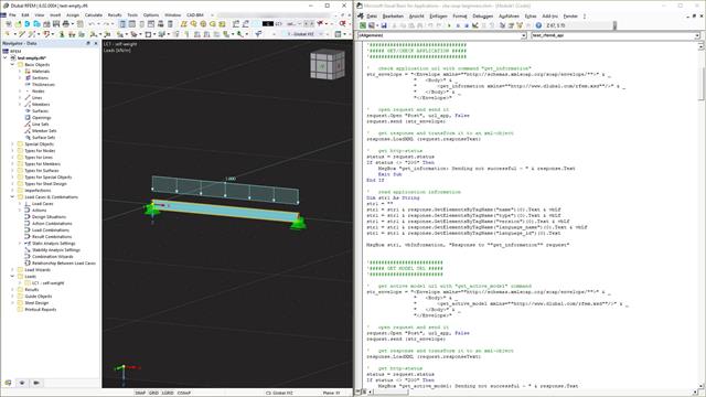
Webservice to komunikacja między maszynami i programami. Komunikacja ta odbywa się za pośrednictwem sieci i dlatego może być wykorzystywana przez dowolny program, który może wysyłać i odbierać ciągi znaków za pośrednictwem protokołu HTTP. Programy RFEM 6 i RSTAB 9 zapewniają interfejs oparty na tych wieloplatformowych usługach sieciowych. Ten tutorial pokazuje podstawy korzystania z języka programowania VBA.
Wraz z programami do analizy statyczno-wytrzymałościowej RFEM 6, RSTAB 9, RSECTION 1 i RWIND 2, Dlubal Software przedstawia nową generację programów do analizy statyczno-wytrzymałościowej. Getreu dem Motto „Statik, die Spaß macht…“ werden den Anwendern universelle Werkzeuge in die Hand gegeben, mit denen alle Anforderungen in der Tragwerksplanung bewältigt werden können. Was sich sonst noch bei Dlubal Software Neues getan hat, erfahren Sie in diesem Artikel.

Rozszerzenie Projektowanie konstrukcji aluminiowych dla RFEM 6 wymiaruje pręty aluminiowe ze względu na stan graniczny nośności i użytkowalności zgodnie z Eurokodem 9. Ponadto możliwe jest wymiarowanie zgodnie z ADM 2020 (norma amerykańska).

Zgodnie z EN 1992-1-1 [1] belka jest prętem, którego rozpiętość jest nie mniejsza niż 3-krotna całkowita wysokość przekroju. W przeciwnym razie element konstrukcyjny należy traktować jako belkę-ścianę. Zachowanie belek-ścian (tj. belek o rozpiętości mniejszej niż 3-krotna wysokość przekroju) różni się od zachowania belek-ścian (tj. belek o rozpiętości trzykrotnie większej niż wysokość przekroju).
Projektowanie belek-ścian jest jednak często konieczne podczas analizy elementów konstrukcyjnych konstrukcji żelbetowych, ponieważ są one wykorzystywane do budowy nadproży okiennych i drzwiowych, podciągów i podciągów, połączeń między płytami dwupoziomowymi oraz konstrukcji ramowych.
Projektowanie belek-ścian jest jednak często konieczne podczas analizy elementów konstrukcyjnych konstrukcji żelbetowych, ponieważ są one wykorzystywane do budowy nadproży okiennych i drzwiowych, podciągów i podciągów, połączeń między płytami dwupoziomowymi oraz konstrukcji ramowych.
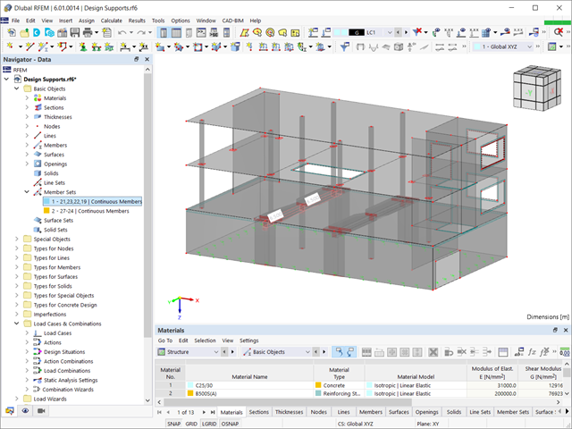
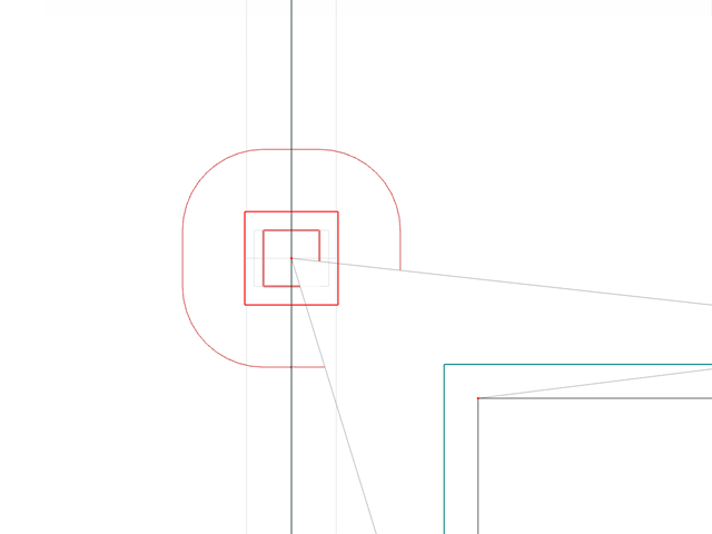
Aby przeprowadzić analizę ugięcia we właściwy sposób, ważne jest, aby "informować" program o dokładnych warunkach podparcia elementu będącego przedmiotem zainteresowania. Definicja podpór obliczeniowych w programie RFEM 6 zostanie wyświetlona dla zbioru prętów żelbetowych.
Zgodnie z rozdz. 6.6.3.1.1 i 10.14.1.2 ACI 318-19 i CSA A23.3-19, program RFEM efektywnie uwzględnia redukcję sztywności prętów betonowych i powierzchni dla różnych typów elementów. Dostępne typy wyboru obejmują zarysowane i niezarysowane ściany, płaskie płyty, belki i słupy. Dostępne w programie mnożniki zaczerpnięto bezpośrednio z tabel 6.6.3.1.1(a) i 10.14.1.2.
Obliczenia na przebicie zgodnie z EN 1992-1-1 należy przeprowadzić dla płyt poddanych obciążeniu skupionemu lub reakcji. Węzeł, w którym przeprowadzana jest analiza nośności na przebicie (tj. w miejscu, w którym występuje problem z przebiciem) nazywany jest węzłem odporności na przebicie. Obciążenie skupione w tych węzłach może zostać wprowadzone przez słupy, siłę skupioną lub podpory węzłowe. Koniec przyłożenia obciążenia liniowego na płyty również jest traktowany jako obciążenie skupione, dlatego należy również kontrolować nośność na ścinanie na końcach, narożach i końcach ścian oraz na końcach lub narożach obciążeń liniowych i podpór liniowych.
Konstrukcje złożone to zespoły elementów konstrukcyjnych o różnych właściwościach. Jednak niektóre elementy mogą mieć te same właściwości w zakresie podpór, nieliniowości, modyfikacji końców, przegubów itp. oraz w obliczeniach (na przykład długości efektywne, podpory obliczeniowe, zbrojenie, klasy użytkowania, redukcje przekroju itp. ). W RFEM 6 istnieje możliwość pogrupowania tych elementów z uwzględnieniem ich wspólnych właściwości i tym samym, mogą być razem modelowane i obliczane.

W tym artykule opisano, w jaki sposób płaska płyta budynku mieszkalnego jest modelowana w programie RFEM 6 i wymiarowana zgodnie z Eurokodem 2. Płyta ma grubość 24 cm i jest podparta na słupach o długości 45/45/300 cm w rozstawie co 6,75 m (rysunek 1). Słupy są modelowane jako sprężyste podpory węzłowe poprzez zdefiniowanie sztywności sprężystej na podstawie warunków brzegowych (rysunek 2). Jako materiały wybrano beton C35/45 i stal zbrojeniową B 500 S (A).
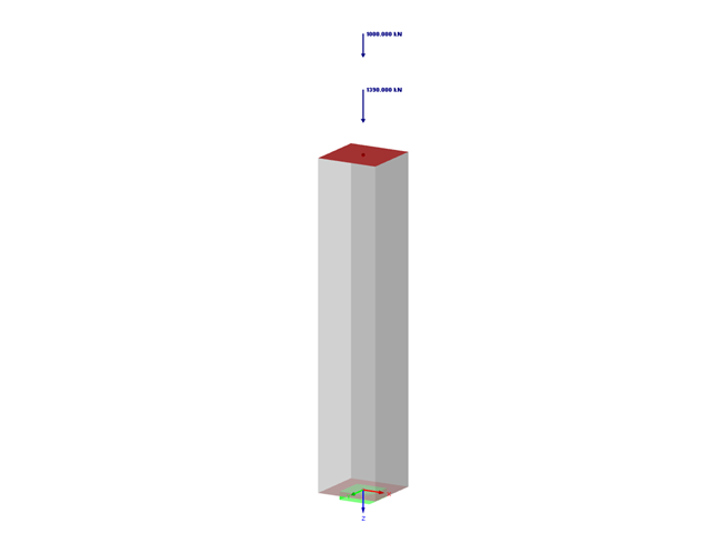
W artykule omówiono elementy prostoliniowe, których przekrój poprzeczny poddany jest osiowej sile ściskającej. Celem tego artykułu jest pokazanie, ile parametrów dotyczących obliczeń słupów betonowych zdefiniowanych w Eurokodach jest uwzględnianych w programie do analizy statyczno-wytrzymałościowej RFEM 5.

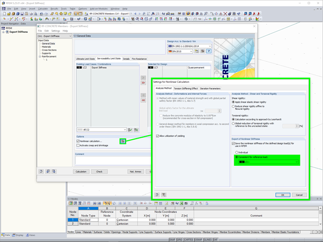
W tym artykule porównujemy obliczenia z obliczeniami w artykule odniesieniem: Wymiarowanie słupów betonowych poddanych ściskaniu osiowemu w RF-CONCRETE Members. Dlatego chodzi o odtworzenie dokładnie tego samego zastosowania teoretycznego, które zostało przeprowadzone w RF-CONCRETE Members, i odtworzenie go w RF-CONCRETE Columns. Celem jest porównanie różnych parametrów wejściowych i wyników uzyskanych za pomocą dwóch modułów dodatkowych do wymiarowania słupowych prętów betonowych.
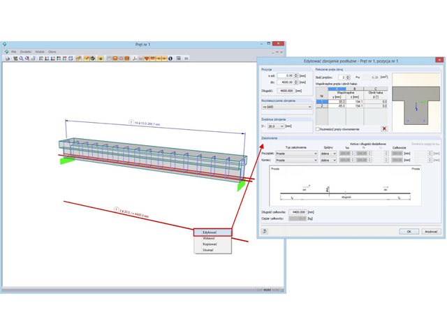
Die Bewehrungsführung beziehungsweise die vorhandene Bewehrung kann auch direkt im 3D-Rendering der Bewehrung editiert werden.
Wird ein Stahlbetonmodell als gemischte Struktur, bestehend aus Flächen- und Stabelementen, abgebildet, so werden für die weitere Bemessung unterschiedliche Module verwendet.
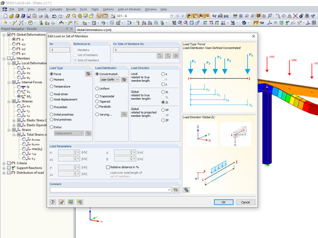
Beliebige Punktlastverläufe treten in der Lastdefinition von Stabtragwerken häufig auf.
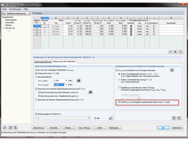
Beim Einsatz von langsam erhärtendem Beton (in der Regel bei dicken Bauteilen) darf die errechnete Mindestbewehrung zur Aufnahmen von Zwangsbeanspruchungen nach EN 1992-1-1, 7.3.2 mit dem Faktor 0,85 abgemindert werden. Bedingung hierfür ist aber, dass der Kennwert für die Festigkeitsentwicklung r = fcm2 / fcm28 nicht größer als 0,3 ist. Zusätzlich sind die Rahmenbedingungen der Anwendungsvoraussetzung für diese Bewehrungsverminderung in den Ausführungsunterlagen explizit festzulegen.
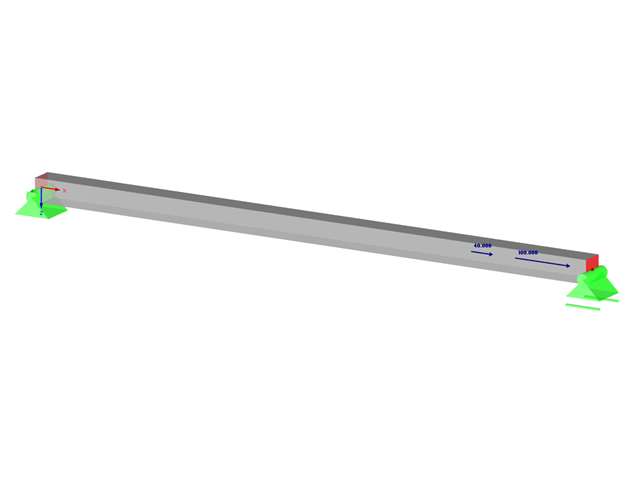
W niniejszym artykule omówiono wyznaczanie zbrojenia belki żelbetowej poddanej jedynie rozciąganiu zgodnie z normą EN-1992-1-1. Celem jest wywołanie obciążenia rozciągającego elementu typu pręt (bez wymuszonych odkształceń) i zwymiarowanie zbrojenia zgodnie z przepisami zawartymi w normie, z wykorzystaniem programu do analizy statyczno-wytrzymałościowej RFEM.