Lookout Tower in Schömberg, Germany
Customer Project
-
01
Timber Column to Platform Pinned Connection (© Ingenieurbüro Braun GmbH & Co. KG)
-
01
Lookout Tower Model (Left) and Deformation Image (Right) in RFEM (© Ingenieurbüro Braun GmbH & Co. KG)
-
01
Connection Steel Stress Analysis in RFEM (© Ingenieurbüro Braun GmbH & Co. KG)
-
01
Model of Lookout Tower in RFEM (© Ingenieurbüro Braun GmbH & Co. KG)
-
01
Lookout Tower in Schömberg During Construction (© Ingenieurbüro Braun GmbH & Co. KG)
-
01
Timber Columns and Bracing (© Ingenieurbüro Braun GmbH & Co. KG)
-
02
Lookout Tower Model (Left) and Deformation Image (Right) in RFEM (© Ingenieurbüro Braun GmbH & Co. KG)
-
02
Timber Column to Platform Pinned Connection (© Ingenieurbüro Braun GmbH & Co. KG)
-
02
Connection Steel Stress Analysis in RFEM (© Ingenieurbüro Braun GmbH & Co. KG)
-
02
Model of Lookout Tower in RFEM (© Ingenieurbüro Braun GmbH & Co. KG)
-
02
Lookout Tower in Schömberg During Construction (© Ingenieurbüro Braun GmbH & Co. KG)
-
02
Timber Columns and Bracing (© Ingenieurbüro Braun GmbH & Co. KG)
-
02
Model of Lookout Tower in RFEM (© Ingenieurbüro Braun GmbH & Co. KG)
-
02
Lookout Tower Made of Timber and Steel | Schömberg, Austria | Ingenieurbüro Braun GmbH & Co. KG | www.braun-ing.de
-
03
Connection Steel Stress Analysis in RFEM (© Ingenieurbüro Braun GmbH & Co. KG)
-
03
Timber Column to Platform Pinned Connection (© Ingenieurbüro Braun GmbH & Co. KG)
-
03
Lookout Tower Model (Left) and Deformation Image (Right) in RFEM (© Ingenieurbüro Braun GmbH & Co. KG)
-
03
Model of Lookout Tower in RFEM (© Ingenieurbüro Braun GmbH & Co. KG)
-
03
Lookout Tower in Schömberg During Construction (© Ingenieurbüro Braun GmbH & Co. KG)
-
03
Timber Columns and Bracing (© Ingenieurbüro Braun GmbH & Co. KG)
-
03
Steel Part of Connection in RFEM (© Ingenieurbüro Braun GmbH & Co. KG)
-
04
Lookout Tower in Schömberg During Construction (© Ingenieurbüro Braun GmbH & Co. KG)
-
04
Timber Column to Platform Pinned Connection (© Ingenieurbüro Braun GmbH & Co. KG)
-
04
Lookout Tower Model (Left) and Deformation Image (Right) in RFEM (© Ingenieurbüro Braun GmbH & Co. KG)
-
04
Connection Steel Stress Analysis in RFEM (© Ingenieurbüro Braun GmbH & Co. KG)
-
04
Model of Lookout Tower in RFEM (© Ingenieurbüro Braun GmbH & Co. KG)
-
04
Timber Columns and Bracing (© Ingenieurbüro Braun GmbH & Co. KG)
-
05
Timber Columns and Bracing (© Ingenieurbüro Braun GmbH & Co. KG)
-
05
Timber Column to Platform Pinned Connection (© Ingenieurbüro Braun GmbH & Co. KG)
-
05
Lookout Tower Model (Left) and Deformation Image (Right) in RFEM (© Ingenieurbüro Braun GmbH & Co. KG)
-
05
Connection Steel Stress Analysis in RFEM (© Ingenieurbüro Braun GmbH & Co. KG)
-
05
Model of Lookout Tower in RFEM (© Ingenieurbüro Braun GmbH & Co. KG)
-
05
Lookout Tower in Schömberg During Construction (© Ingenieurbüro Braun GmbH & Co. KG)
This multi-material tower structure includes mainly timber and steel elements. Only the foundation and attached rigid columns were constructed as reinforced concrete.
Owner |
Municipality of Schömberg, Germany www.schoemberg.de |
Structural Analysis |
Ingenieurbüro Braun GmbH & Co. KG www.braun-ing.de |
Concrete Structure |
Pfirmann Industriebau GmbH & Co. KG www.pfirmann-bau.de |
Timber and Steel Structures, Elevator, Electrical Engineering |
Stahlbau Nägele GmbH www.stahlbau-naegele.de |
Model Data
Model
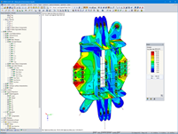
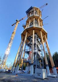
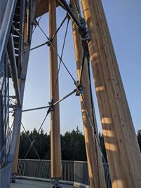
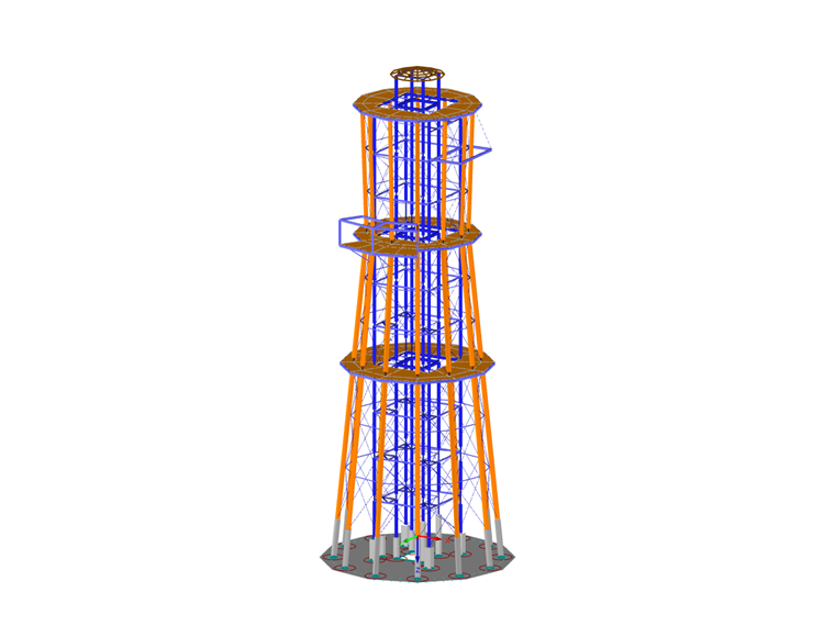
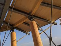
The lookout tower floor plan is formed by a regular dodecagon, which is made of twelve radial timber columns. The columns further attach to the platform levels with a pinned connection. At the base point, the timber columns are supported by the approximately 17.76-foot-high rigid reinforced concrete columns. The structure’s lateral stiffness includes a diagonal tension member bracing system with a total of six circumferential steel pipe compression rings. The three platforms are flat cross-laminated timber (CLT) panels, each designed as a horizontal wall.
Inside the tower is a frame-like steel structure which includes vertical and horizontal I-sections and tension member cross bracing. The main platform elevations are 66, 115, and 164 ft above ground. An additional partial platform cantilever is constructed 148 ft above ground. This partial platform covers approximately 1/3 of the available floor plan area and houses the zip-line entrance. Two panels are enlarged on the central platform at a height of 115 ft. This is where the zip-line entry is located.
The tower’s foundation is a flat, twelve-sided floor slab. Attached are circular column supports which further connect to the structure’s timber columns. The staircase steel columns, similar to the timber columns, are supported by the foundation’s fixed square columns.
Project Location
75328 SchömbergKeywords
Lookout tower Timber tower Steel tower Mixed construction
Write Comment...
Write Comment...
Contact Us
Do you have further questions or need advice? Contact us via phone, email, chat, or forum, or find suggested solutions and useful tips on our FAQ page, available 24/7.

New
Evaluating and Documenting Steel Joints Analysis Results in RFEM 6
With the RFEM 6 add-on Steel Joints, you can analyze steel connections by using an FE model. This article demonstrates how to evaluate and document the steel joints analysis results.

New
- The design of the connection components is performed according to Eurocode EN 1993-1-8
- After activating the Add-on, the design situations for Steel Connections must be activated in the "Load cases and Combinations" dialog box
- For the design of the connection stability (Buckling), it is necessary to have the Add-on Structure Stability activated
- The calculation can be started via the table or via the icon in the top bar
-
How do I set a release for warping?
- How can I define a warping spring or a warping restraint?
- At which point on a cross-section are the supports and loads assumed for the calculation with warping torsion?
- The limit stress is activated, but my stress ratio is “non-designable” in the Stress-Strain Analysis add-on. What could be the reason?
- How can I deactivate the 7th degree of freedom for certain members or cross-sections only?
- How can I define a warping spring or a warping restraint?