Construction of the ÖkoFEN Headquarters, Saint Baldoph, France
Customer Project
In order to meet the increasing demand arising from growing staff numbers, the company OköFEN, which specializes in wood pellet boilers, conducted the construction of new premises for its French head office. This project is rooted in an environmental approach featuring a structure entirely made of French wood, biobased insulation in cellulose wadding, and a significant supply of natural light thanks to its multiple openings.
Investor | ÖkoFEN Real Estate |
Architect | Atelier 17C Architectes |
Engineering Office |
CBS-CBT |
Carpenter | Lifteam |
Model Parameters
Model
Design Process
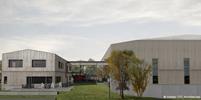
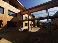
This project features 2 buildings which are connected to each other by a metal footbridge.
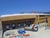
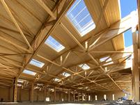
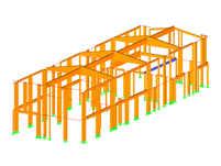
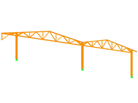
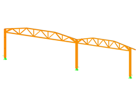
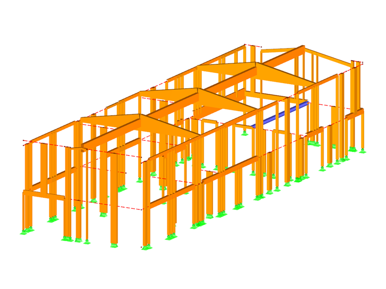
The first part consists of a storage area measuring 150.92x203.41 ft, made of truss frames of the Ariane© type (solid timber 3.15 inches wide and joints with plywood gusset and spikes) with ranges of 65.62 and 85.30 ft and cantilevers of 18.37 ft. The structure relies on foundations made of isolated studs, connected by prefabricated stringer beams, allowing the elevation from the ground of the non-load-bearing timber framing facades.
The second part consists of an office building extending from the ground floor to the first floor of approximately 32.81x98.43 ft made of timber frame walls and roof boxes industrially prefabricated with cellulose wadding insulation, also factory-made. The timber frame is elevated from the ground by foundations made of prefabricated stringer beams. The floors of the southern offices are made of O'Portune slabs with a range of 32.81 ft.
All the facades are covered with natural timber cladding.
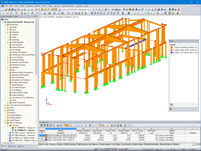
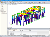
Structural Design Software
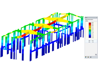
The structural design of the 2 buildings was carried out using RFEM software. The building is located in a seismic region of magnitude 4, which required design checks under seismic loads generated with the RF-DYNAM Pro add-on.
The entire timber structure of the warehouse area was checked in the RF-TIMBER Pro add-on according to Eurocode 5.
The modeling of the office area was especially necessary for dimensioning the walls subjected to seismic loads. In order to generate this modeling, the timber frame walls were converted into equivalent members reproducing the stiffness of a wall. Such an approach enabled evaluation of the forces transmitted within each wall, hence justifying the bracing of the building.
The steel footbridge was also modeled in RFEM and the member design was performed thanks to the RF-STEEL EC3 add-on.
Project Location
Keywords
Timber structure RFEM RF-TIMBER Pro RF-DYNAM Pro RF-STEEL EC3
Write Comment...
Write Comment...
Contact Us
Do you have further questions or need advice? Contact us via phone, email, chat, or forum, or search the FAQ page, available 24/7.

Timber Member Compression Perpendicular to the Grain acc. to NDS 2018 and CSA O86:19
A standard scenario in timber member construction is the ability to connect smaller members by means of bearing on a larger girder member. Additionally, member end conditions may include a similar situation where the beam is bearing on a support type. In either scenario, the beam must be designed to consider the bearing capacity perpendicular to the grain according to the NDS 2018 (Sect. 3.10.2) and the CSA O86:19 (Clause 6.5.6 and 7.5.9). In the new generation RFEM 6 and Timber Design add-on, the added feature 'design supports' now allows users to comply with the NDS and CSA bearing perpendicular to the grain design checks.
-
The load distribution on my members looks different when using the Load Transfer surface vs. the Load Wizards. What is the reason?
- How can I efficiently define line hinges on several surfaces?
- Why cannot I define a rotation when defining layers?
- How do I create an imperfection based on a mode shape in RFEM 6?
- Why does the eHORA map of Austria give different snow loads than your Geo-Zone tool?
- Why does the load wizard "Member Load from Area Load" give unnecessary concentrated loads?
- How can I carry out case-related design for different load situations?
- How can I modify the lamella thickness for a glulam section in RFEM 6?
- How do I define a member as a cantilever and not as supported at both ends for serviceability or deflection design?
- I would like to export nodal support forces of several load cases, load combinations and result combinations into an Excel spreadsheet in RFEM 6. How should I proceed?
- How can I efficiently define line hinges on several surfaces?