


This article deals with the use of horizontal rigid diaphragms, which are used mainly for concrete floor slabs. This type of modeling offers several advantages. One of the advantages is that the calculation speed is significantly better, because the masses of each story are concentrated in one point. The results are transparent and can be evaluated story by story, as well as being documented in a clearly arranged format.
RFEM offers nodal constraints for this purpose. A nodal constraint establishes the relation between displacements and rotations between two or more nodes. Below this article, you can download the document that describes this option in detail.
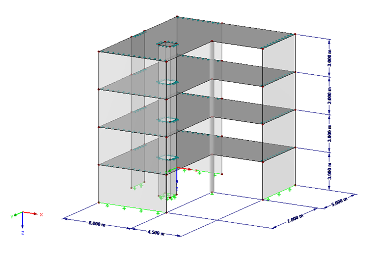
This article describes the use of rigid diaphragms in RFEM by means of an example. The structure is a 4-story building construction that is regular in the front view, but not in the ground plan. The walls are hinged to the floor slabs.
Modeling Rigid Diaphragm in RFEM
The masses of each single story are concentrated in its center of gravity. To determine it, select the "Center of Gravity and Info…" function, which you can open by selecting all the objects in the story using the shortcut menu. With this option, you can generate a node in the story's center of gravity. You can also use this option to determine the mass of the story at the same time. These masses are listed in the table below. The generated nodes for each story must then be moved to the diaphragm of the floor slabs (modification of the Z-coordinate).
In this example, additional permanent loads, imposed loads, and snow loads on the surfaces were defined. To be able to consider them later, you have to convert them into a total mass per story.
| 4th Floor | 3rd Floor | 2nd Floor | 1st Floor | Sum | |
|---|---|---|---|---|---|
| Self-weight | 97,631.3 kg (107.62 US tons) | 97,006.3 kg (106.93 US tons) | 97,006.3 kg (106.93 US tons) | 97,006.3 kg (106.93 US tons) | 388,650.2 kg (428.41 US tons) |
| Fixed loads | 18,900.0 kg (20.83 US tons) | 18,700.0 kg (20.61 US tons) | 18,700.0 kg (20.61 US tons) | 18,700.0 kg (20.61 US tons) | 75,000.0 kg (82.67 US tons) |
| Imposed loads | 47,250.0 kg (52.08 US tons) | 46,750.0 kg (51.53 US tons) | 46,750.0 kg (51.53 US tons) | 46,750.0 kg (51.53 US tons) | 187,500.0 kg (206.68 US tons) |
| Snow loads | 14,175.0 kg (15.62 US tons) | 14,175.0 kg (15.62 US tons) |
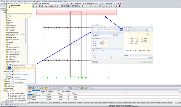
When all masses have been documented, the floor slabs (including all openings and line hinges) can be deleted and replaced with nodal constraints. We recommend dividing the connection lines of the walls by means of nodes so the connection can be modeled more realistically. In this example, we chose the distance of a finite element. Entering the nodal constraint is shown in Image 02. We select "Diaphragm Constraint" as the type. Make sure that you also select the center of gravity of each story.
In order to be able to evaluate the results at the nodes of the centers of gravity later, coupling members (hinge-hinge) are defined, each vertically from the center of gravity of a story.
If the nodal constraints are defined, you can enter the masses in the RF-DYNAM Pro add-on module. For this purpose, three mass cases are created, in which only manually defined nodal masses are entered (masses as listed in the table). The masses are applied to the center of gravity of each story.
In the following text, the response spectrum analysis with generation of equivalent loads will be used. The natural vibration analysis is performed with eight eigenvalues for the X- and Y-directions. With these settings, all available mode shapes are calculated; all these are also used for the response spectrum analysis. Thus, you get an effective modal mass factor of 1.0 in both directions.
Result Evaluation and Comparison with Conventional Modeling
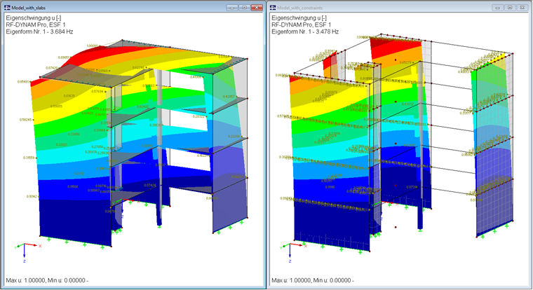
The first two mode shapes are identical with respect to their direction in the two considered models and differ only slightly in the natural frequencies. In Image 03, the conventional model with floor slabs is shown on the left and the model with nodal constraints is shown on the right. The first mode shape is displayed.
To evaluate the results of the response spectrum analysis, it is useful to model a result beam, as explained in this article:
KB 1521 | Determination of Transversal Shear Under Seismic Loads
The results are listed in the following table. For this example, only the X-direction is shown (result combination: result envelope X).
| Model with Floor Slabs | Model with Nodal Constraints | Deviation | |
|---|---|---|---|
| Natural frequency (Mode 1) | 3.772 Hz | 3.478 Hz | 6.5% |
| Natural frequency (Mode 2) | 5.688 Hz | 5.472 Hz | 3.8% |
| Transversal shear second floor 3 (Vz) | 138.8 kN | 178.4 kN | -28.5% |
| Transversal shear second floor 2 (Vz) | 90.3 kN | 104.0 kN | -15.2% |
| Transversal shear second floor 1 (Vz) | 56.9 kN | 62.0 kN | -9.0% |
| Transversal shear first floor (Vz) | 28.9 kN | 25.4 kN | 12.1% |
| Story drift second floor 3 (in X-direction) | 0.9 mm (0.03 in) | 1.1 mm | -22.2% |
The results differ slightly; the model with the nodal constraints has larger forces or deformations especially at the top floor, which are slightly smaller on the lowest floor.
This modeling represents a simplification of the entire system and has advantages in terms of performance, further processing, and traceability. This method is very well suited to most seismic analyses, and represents an alternative to the conventional method.
