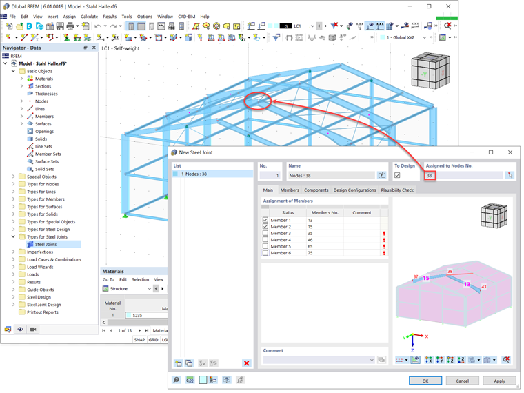
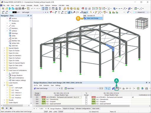
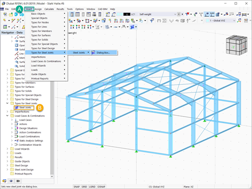
First, it is important to activate the Steel Joints add-on in the Base Data of the model. This way, Types for Steel Joints is available in the Navigator, and you can create new joints by double-clicking the Steel Joints entry. Alternatively, you can open the New Joint dialog box via Insert → Types for Steel Joints → Steel Joints → Dialog Box (Image 1).

In the same fashion as when you define the steel joint components manually, it is necessary to select the node of the RFEM model associated with the steel connection to be created. On the basis of the node selection, the program recognizes and assigns the connecting members as shown in Image 2. By default, all members are selected, but you can unselect the members that will not belong to the steel connection to be designed.
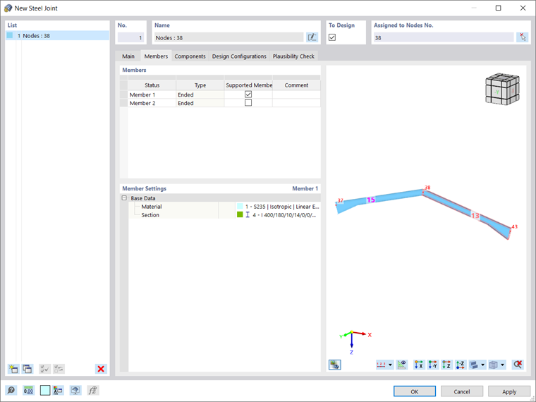
It is necessary to define which member is supported, since the FEA requires at least one member to be supported, whereas the other one should contain the loading in terms of internal forces. This can be done in the Members tab of the New Steel Joint dialog box. In this tab, you can also adjust the base settings of the members such as Material and Section (Image 3).
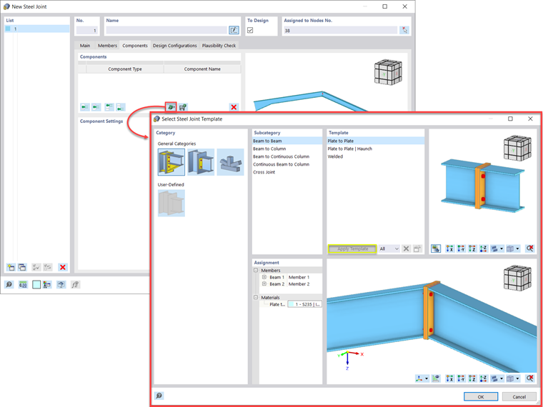
Next, you can define the components of the steel connection. As mentioned previously, the steel joint templates offered in the program’s library will be used to create the connection of interest. It is important to mention that the library is continuously enlarged. The available templates are accessible via the icon indicated in Image 4.
They are grouped in three general categories: rigid, pinned, and truss. For each of them, there are various subcategories in which the templates are organized: beam-to-beam connections, beam-to-column connections, column-to-beam connections, cross joints, K joints, and so on. Alternatively, you can choose your own user-defined steel joint templates stored beforehand.
For the connection of interest in this article, a plate-to-plate joint template is chosen to create the rigid beam-to-beam connection between the selected members. You can select the template by clicking the “Apply Template” button. Then, the connecting members are automatically assigned as beams 1 and 2, but you can adjust this together with the material of the plate (Image 4).
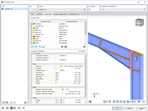
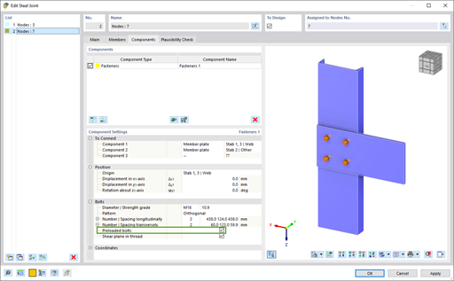
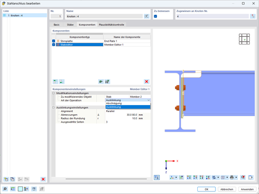
The component settings can be edited further in the Components tab of the New Steel Joint dialog box (Image 5). First, you can choose the position including the origin (either half-angle or perpendicular for this particular joint type), axial displacement, and rotation around the x, y, and z axes. Next, the thickness of the plate can be adjusted, and the plate can be defined in terms of its dimensions and positions on one hand, or offsets on another.
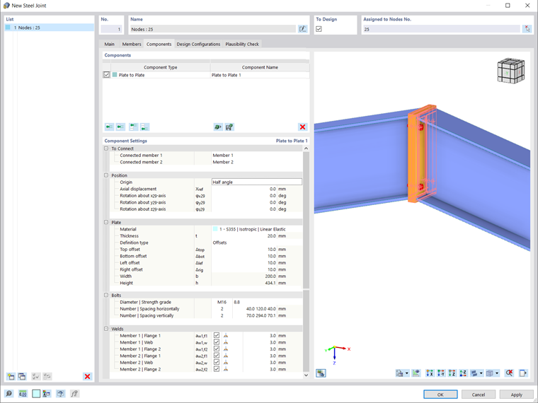
The settings for the other components such as bolts and welds can also be adjusted. For instance, the diameter and strength grade of the bolts, as well as the number and spacing (horizontally and vertically) can be defined. In a similar manner, fillet, double fillet, and butt welds can be defined on the front or rear side of flanges and webs.
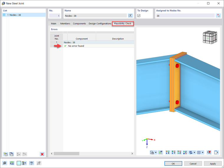
Next, you can run a plausibility check as shown in Image 6 to examine the connection. If the program detects missing data, plate collisions, incorrect welds, and so on, they will be listed as errors. Otherwise, the “No error found” message will be displayed, meaning that the connection is well defined.
You can also assign the ultimate configuration for the design, which will be considered in an upcoming Knowledge Base article.
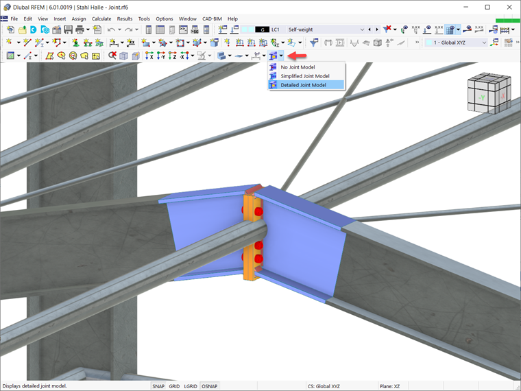
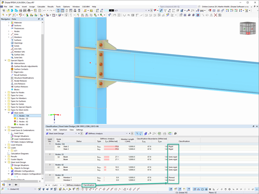
Once inserted, the steel joint is available in the RFEM working window. In Image 7, for instance, the detailed steel joint model is displayed; nevertheless, you can also choose to display simplified joint models, or not to display joint models at all.


.jpg?mw=350&hash=91f398b559b26a6ac36fd7ecdf5e395e7b9b856d)


.png?mw=600&hash=49b6a289915d28aa461360f7308b092631b1446e)


