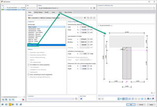
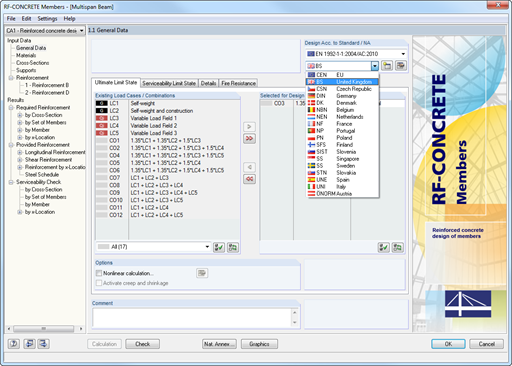
After the calculation, the module shows clearly arranged tables listing the required reinforcement and the results of the serviceability limit state design. All intermediate values are included in a comprehensible manner.
The results of RF‑CONCRETE Members are displayed as result diagrams of each member. The reinforcement proposals of the longitudinal and the shear reinforcement, including sketches, are documented in accordance with current practice. It is possible to edit the reinforcement proposal and to adjust, for example, the number of members and the anchorage. The modifications will be updated automatically. A concrete cross‑section, including reinforcement, can be visualized in a 3D rendering. This way, the program provides an optimal documentation option to create reinforcement drawings, including steel schedule.
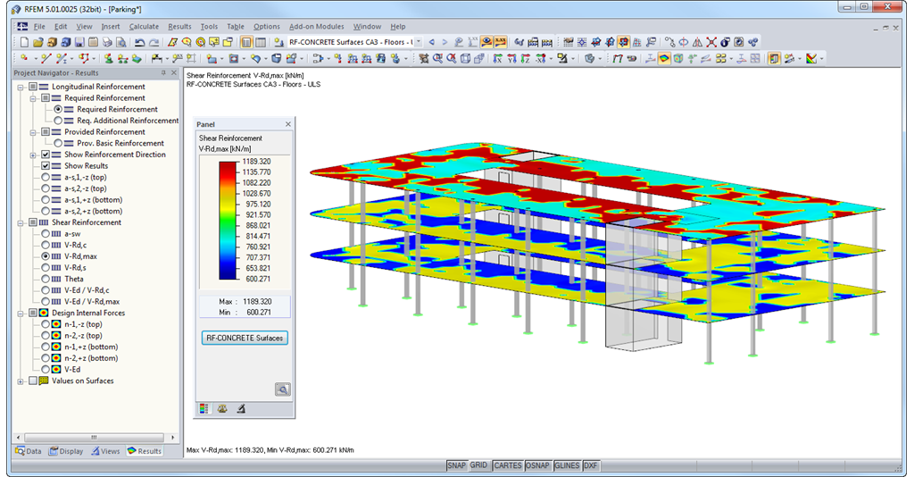
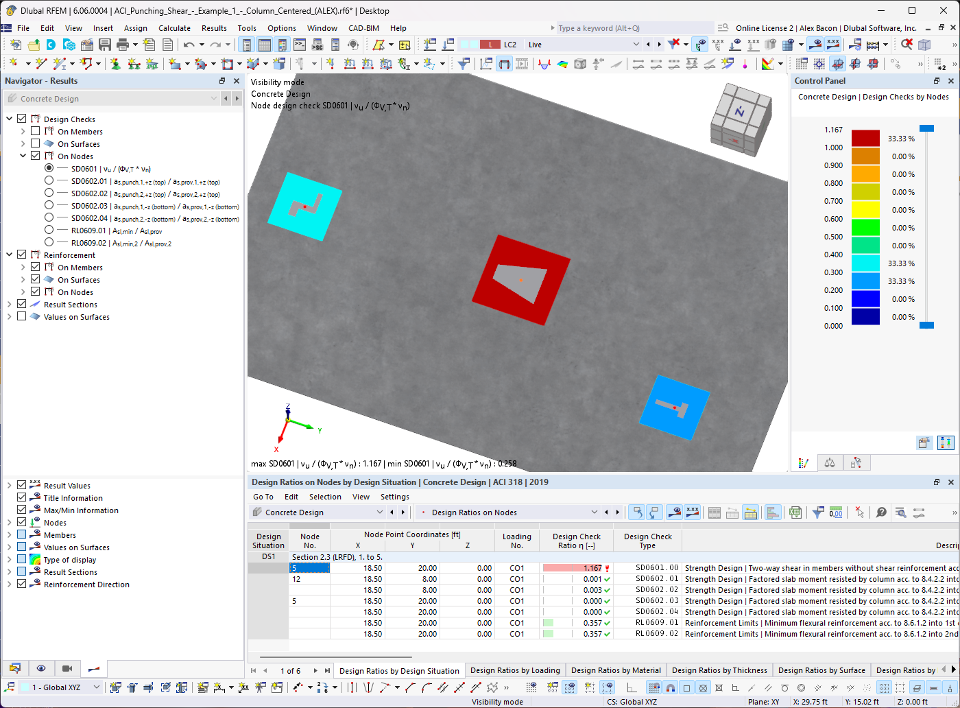
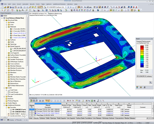
The results of RF-CONCRETE Surfaces can be displayed graphically as isolines, isosurfaces, or numeric values. It is possible to sort the longitudinal reinforcement display by required reinforcement, required additional reinforcement, provided basic or additional reinforcement, and provided total reinforcement. The isolines of the longitudinal reinforcement can be exported as a DXF file for further use in CAD programs as a basis for reinforcement drawings.