


Mouse Control
The mouse functions follow the Windows standards: When you click on a structure or load object with the left mouse button, you select it. Double-click on the object to open its "Edit Model" dialog box. You can use this functionality not only for the graphic objects in the work window, but also for the object entries in the navigator.
When you hold down the Ctrl key, you can select several objects by clicking one after the other. You can remove an object from the selection by holding down the Shift key.
When you right-click on an object, you open its shortcut menu. The menu offers object-related commands and functions. Shortcut menus are available not only in the graphics, but also in the navigator.
When you scroll using the mouse wheel, you maximize or minimize the displayed model. The current pointer position serves as the center of the zoom area.
With the scroll wheel pressed, you can move the scene. When you additionally hold down the Ctrl key, you can rotate the model's view. Rotating is also possible by using the scroll wheel while holding down the right mouse button.
Some mouse display options are indicated by a mouse icon; see table below.
|
|
Move the scene around, press mouse wheel button |
|
|
Rotate scene, press mouse wheel button + right mouse button (ctrl + mouse wheel button) |
|
|
Zoom the scene, press shift + mouse wheel button |
View Buttons
You can switch quickly and easily between the default views using the functions in Toolbar.
![]()
The buttons have the following functions:
|
|
Set view |
|
|
Shows previous view |
|
|
Zoom with a rectangle on any object in the scene |
|
|
View all the models in the scene |
|
|
Select center of rotation |
|
|
Reset the center of rotation to the default position |
|
|
Show/hide center of rotation |
|
|
Isometric view |
|
|
Perspective view |
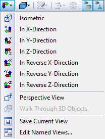
Next is the view menu, where you can view the model in the x, y, z directions (also in reverse directions) and save or edit the view.
Rendering
There are several ways to represent the model graphically. Use the list button to switch quickly between the three basic display types.
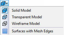
The functions of the buttons are as follows:
|
|
Displays the rendered model as a solid model |
|
|
Displays the rendered model in transparent view |
|
|
Displays the line model |
|
|
Displays mesh edges in surfaces |
3D Viewbox
In the graphics, a 3D viewbox can be displayed via "View" in the main menu. Clicking on the viewbox, the model can be viewed easily from different sides.
