


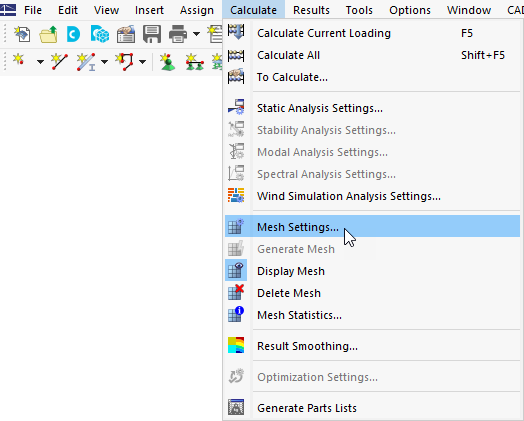
To open the "Mesh Settings" dialog box, click Mesh Settings on the Calculate menu.
Then select the Wind Simulation tab.

The setting in this tab is Global for the entire model. Specific wind simulation settings for individual objects overwrite this Global setting.
Shrink Wrapping
In this section, shrink wrappings (SW) are defined for the entire model. The model is divided into two groups.
The "Main structure" group contains all relevant RFEM objects (members, surfaces, and solids). A finer default SW is assigned to this group.
The "Surrounding objects" group contains IFC files and visual objects. Although the default SWs are assigned to these groups, they can be edited or a new SW can be created and assigned.
For the "Terrain", the SW is not yet available.
Geometry Representation in Wind Tunnel
As explained in Chapter Model for Wind Simulation, an FEM model is not suitable for CFD calculation. Instead, the outer shape of the structure should be used and eventually wrapped. RFEM objects creating this shape can be adjusted in order to consider required properties or to improve performance.
For members, the Member level of detail can be set from 0 to 10. Member level of detail 10 exports members with an accurate shape (i.e., cross-section). 0 exports the member shape simplified with a rectangular section that envelops the outlines of the original shape. For further details, see FAQ 4165.
Wind flow through hollow cross-sections does not usually play an important role in civil engineering. By default, hollow cross-sections are represented by their outer shape. Deactivating the "Use only external surface for hollow sections" option enables export of the hollow shape.

The "Consider surface thickness above" option enables you to export surfaces considering their thicknesses from a defined threshold value.
Options
Terrain
The "Terrain" option enables you to use the terrain geometry defined in RFEM 6 as the bottom of the wind tunnel. The terrain model can be created in the "Base Data" on the "Terrain" tab using planes, tables, or an IFC file. When an IFC file is used as terrain in Base Data, it is automatically excluded from being exported to the calculation of wind simulation among surrounding structures. Terrain defined by a horizonal plane can be moved up or down to create an offset.

Keep results
The "Keep wind simulation results if mesh is deleted" option makes it possible to keep the RWIND results even after deleting the finite element mesh. The RWIND results will be deleted only by:
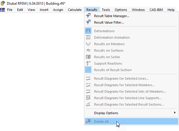
- Using the "Delete All" option in the "Menu" toolbar
- unchecking the option "Keep wind simulation if mesh is deleted"
- deleting LC
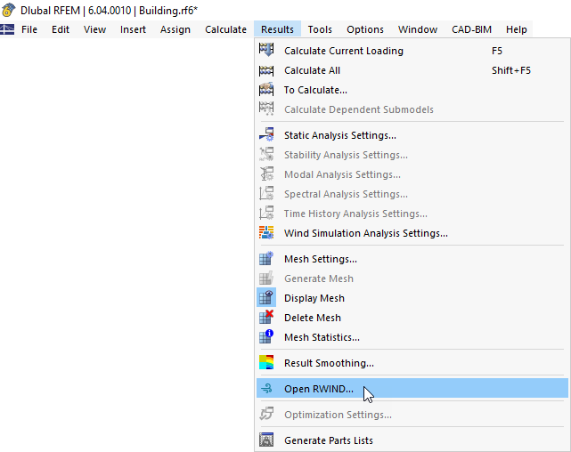
- deleting RWIND results directly in RWIND (via "Open in RWIND")
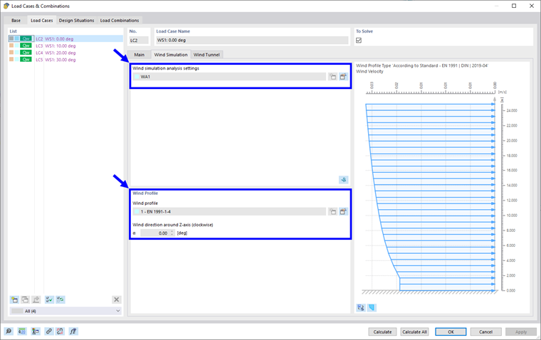
- changing the input parameters for RWIND (wind simulation analysis settings, wind profile, or types for wind simulation)
This option is disabled by default, as it is very dangerous and only informed users should be allowed to use it. When the model data are changed, the question arises as to how to distribute the "old" loads adequately across the geometry of the "new" model. Users must judge for themselves whether the results are still acceptable.
Silent or interactive mode
The last option "Run RWIND in silent mode" allows you to run CFD calculation only in the background of RFEM without opening RWIND.
By disabling this option, an interactive mode is active. After FE mesh generation, RWIND is opened and the model and simulation parameters can be edited there directly. Shrink wrapping, FE mesh, and more can be displayed. After the wind flow is calculated, results can be displayed, including some post-processing features not yet available in RFEM. After saving and closing RWIND, the results are imported back to RFEM, the structural analysis is performed, and the result display in RFEM follows in the same way as in the silent mode.