


Deformations and Internal Forces
Chapter Results of the RFEM manual gives an overview of the different types of results. Use the "Navigator - Results" or the toolbar buttons to display the deformations of surfaces and members or to select specific internal forces of surfaces or members.
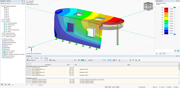
You can verify the plausibility of the applied wind loads by checking the global deformations, for example. The "Summary" table gives you an overview of the sums of loads and support forces, as well as of the global resultants (see the image Deformations above).
Distribution of Loads
1D FE Elements
In RWIND, members are represented by their surface. After the calculation, the member axes are divided into segments, the resulting pressures on surfaces belonging to these segments are integrated, and the resulting force is assigned to each member segment (see Chapter Member forces). RFEM 6 imports these member forces, and according to the "Member load distribution" in "Wind simulation analysis settings", applies the member load as a concentrated or continuous (uniform or trapezoidal) force load (see Chapter Main).
Load using RWIND and Ponding
In the "Load using RWIND and Ponding" section, the pressure results from the RWIND 3 simulation are extrapolated to a finite element mesh (FEM) generated by RFEM 6; the resulting values are summed up from both surface sides and displayed in a global or local coordinate system as a surface load.
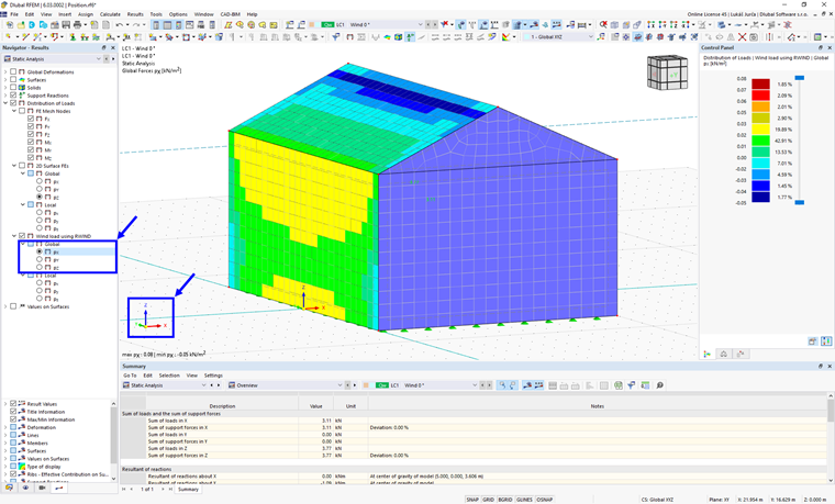
The global forces pX, pY and pZ are related to the global coordinate system shown in the lower left corner of the screen; see image above.
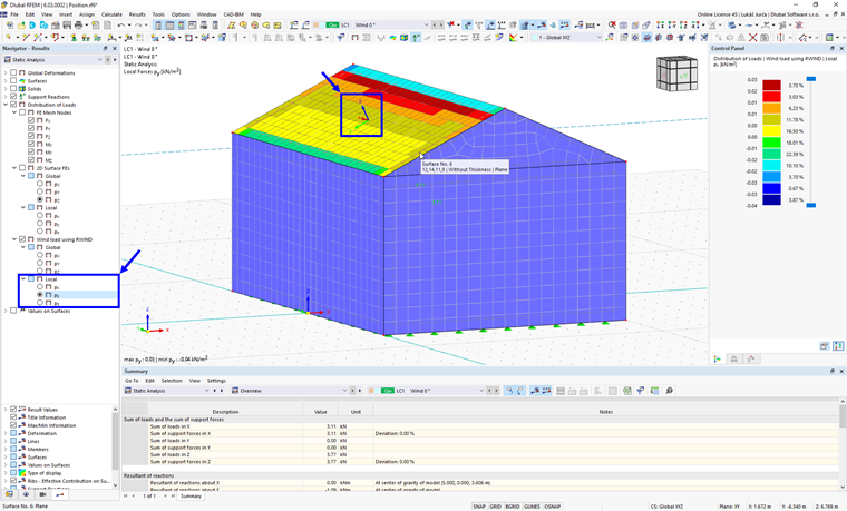
Local forces px, py and pz, on the other hand, are related to the local coordinate system of the surface; the coordinate system is displayed when the mouse cursor is moved over the surface, as shown in the image above.