38 Wyniki
Wyświetl wyniki:
Sortuj według:

Blachownica to ekonomiczny wybór w przypadku konstrukcji o dużych rozpiętościach. I-section steel plate girder typically has a deep web to maximize its shear capacity and flange separation, yet thin web to minimize the self-weight. Due to its large height-to-thickness (h/tw) ratio, transverse stiffeners may be required to stiffen the slender web.

W rozszerzeniu Projektowanie konstrukcji stalowych dla programu RFEM 6 dostępne są trzy typy ram sprężystych (zwykłe, pośrednie i specjalne). Wyniki obliczeń sejsmicznych zgodnie z AISC 341-22 są podzielone na dwie sekcje: wymagania dotyczące prętów i połączeń.
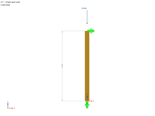
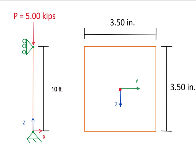
Rozszerzenie Wymiarowanie drewna umożliwia wymiarowanie słupów drewnianych zgodnie ze standardową metodą ASD 2018 NDS. Dokładne wyznaczenie nośności na ściskanie oraz współczynników redukcyjnych dla prętów drewnianych jest konieczne dla bezpieczeństwa konstrukcji. Poniższy artykuł weryfikuje maksymalną wytrzymałość na wyboczenie krytyczną obliczoną w module rozszerzeniowym Wymiarowanie drewna przy użyciu równań analitycznych krok po kroku zgodnie z normą NDS 2018, w tym współczynników dostosowania przy ściskaniu, skorygowanej wartości obliczeniowej na ściskanie i końcowego stopnia wyboczenia.

W rozszerzeniu Projektowanie konstrukcji stalowych dla programu RFEM 6 dostępne są trzy typy ram sprężystych (zwykłe, pośrednie i specjalne). Wyniki obliczeń sejsmicznych zgodnie z AISC 341-16 są podzielone na dwie sekcje: wymagania dotyczące prętów i połączeń.

Obliczenia zwykłej ramy stężonej koncentrycznie (OCBF) oraz SCBF (specjalnej konstrukcji szkieletowej stężonej koncentrycznie) można przeprowadzić w rozszerzeniu Projektowanie konstrukcji stalowych dla programu RFEM 6. Wyniki obliczeń sejsmicznych zgodnie z AISC 341-16 i 341-22 są podzielone na dwie sekcje: Wymagania dotyczące prętów i połączeń.
Blachownica to ekonomiczny wybór w przypadku konstrukcji o dużych rozpiętościach. I-section steel plate girder typically has a deep web to maximize its shear capacity and flange separation, yet thin web to minimize the self-weight. Due to its large height-to-thickness (h/tw) ratio, transverse stiffeners may be required to stiffen the slender web.
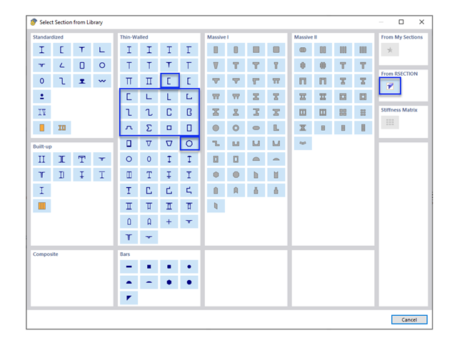
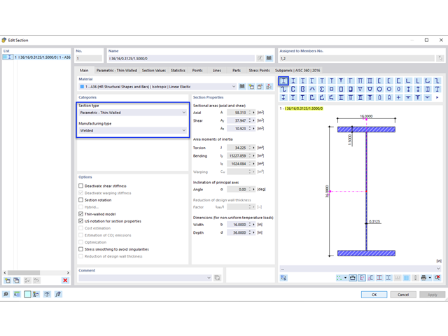
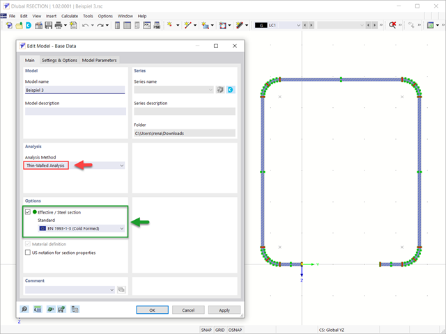
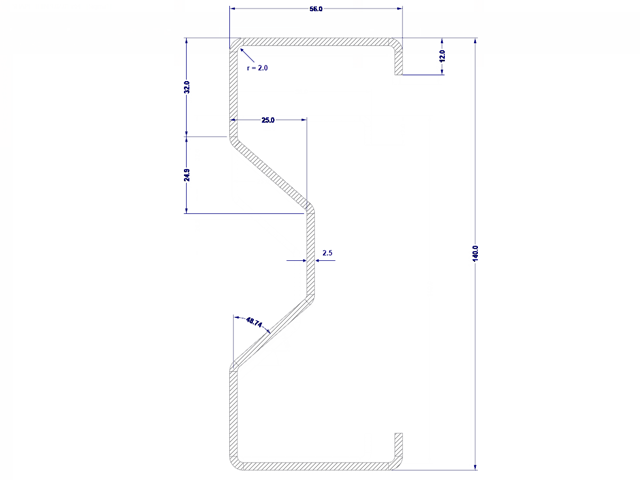
W obliczeniach konstrukcji stalowych formowanych na zimno często wymagane są niestandardowe przekroje. In RFEM 6, the custom section can be created using one of the “Thin-Walled” sections available in the library. For other sections that do not meet any of the 14 available cold-formed shapes, the sections can be created and imported from the standalone program, RSECTION. For general information on AISI steel design in RFEM 6, refer to the Knowledge Base article provided at the end of the page.
Celem zastosowania programów RFEM 6 i Blender z rozszerzeniem Bullet Constraints Builder jest uzyskanie graficznej reprezentacji zawalenia się modelu na podstawie rzeczywistych danych dotyczących właściwości fizycznych. Program RFEM 6 służy jako źródło geometrii i danych do symulacji. Jest to kolejny przykład, dlaczego ważne jest, aby nasze programy utrzymywać jako tak zwane BIM Open, aby umożliwić współpracę między różnymi dziedzinami oprogramowania.
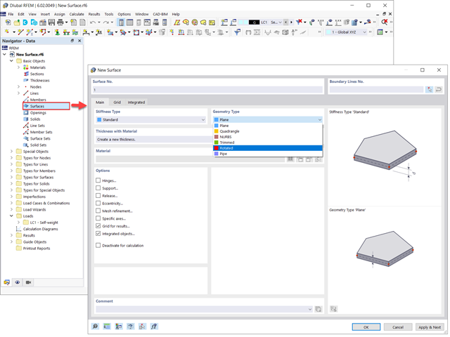
Powierzchnie w modelach budynków mogą mieć różne rozmiary i kształty. W programie RFEM 6 można uwzględnić wszystkie powierzchnie, ponieważ program umożliwia definiowanie różnych materiałów i grubości, a także powierzchni o różnej sztywności i typie geometrii. W tym artykule skupiono się na czterech z następujących typów powierzchni: obrócony, przycięty, bez grubości i przeniesienia obciążenia.
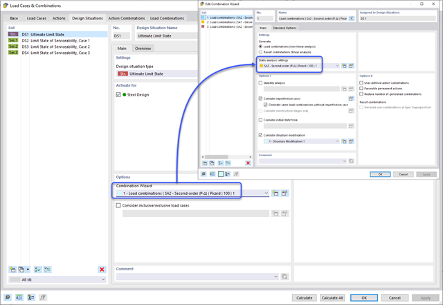
Metoda CSA S16:19 Skutki stateczności w analizie sprężystej w Załączniku O.2 stanowi alternatywę dla metody Uproszczonej analizy stateczności z punktu 8.4.3. W tym artykule zostaną opisane wymagania załącznika O.2 i zastosowania w RFEM 6.

Wymiarowanie prętów stalowych formowanych na zimno zgodnie z AISI S100-16 jest teraz dostępne w programie RFEM 6. Design can be accessed by selecting “AISC 360” as the standard in the Steel Design add-on. “AISI S100” is then automatically selected for the cold-formed design (Image 01).
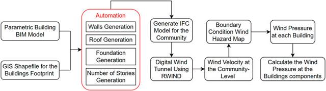
W artykule tym opracowano nowatorskie podejście do generowania modeli CFD na poziomie miejscowości poprzez połączenie modelowania informacji o budynku (BIM) i systemów informacji geograficznej (GIS) w celu zautomatyzowania generowania trójwymiarowego modelu terenu o wysokiej rozdzielczości, który zostanie wykorzystany jako dane wejściowe dla cyfrowego tunelu aerodynamicznego z wykorzystaniem RWIND.
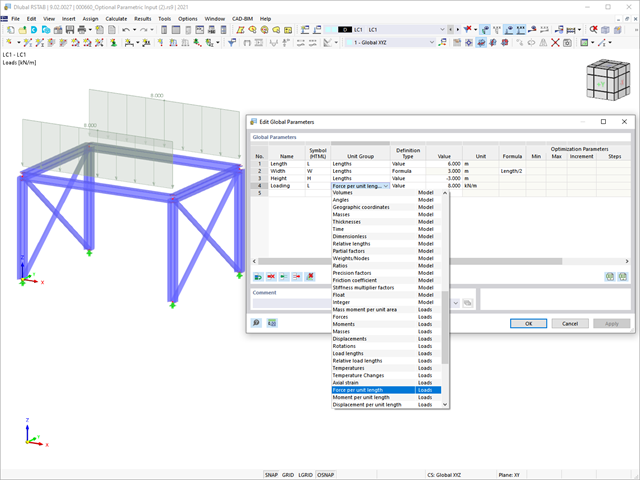
W tym artykule podsumowano zalety pracy ze sparametryzowanymi modelami w programach RFEM 6 i RSTAB 9.
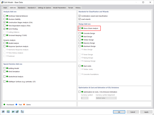
W tym artykule pokazano, jak zarządzać danymi wejściowymi dla konfiguracji obliczeń prętów i powierzchni w rozszerzeniu Analiza naprężeniowo-odkształceniowa.
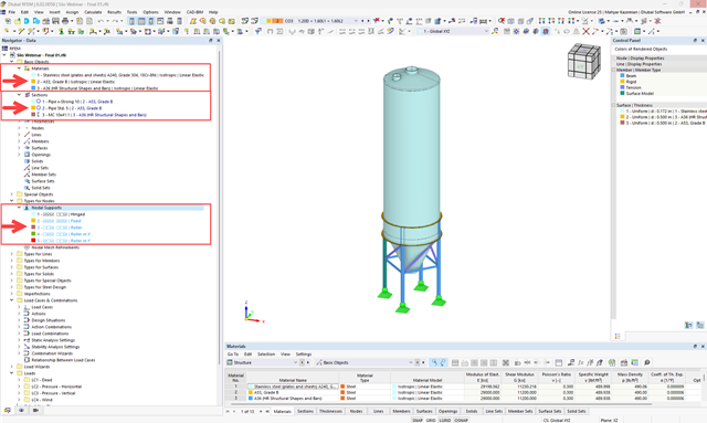
Samodzielny program RSECTION służy do określania właściwości przekrojów i przeprowadzania analizy naprężeń dla przekrojów cienkościennych i masywnych. Program może być połączony zarówno z RFEM, jak i RSTAB, dzięki czemu przekroje z RSECTION są również dostępne w bibliotece RFEM i RSTAB. Podobnie siły wewnętrzne z programów RFEM i RSTAB można importować do programu RSECTION.
Samodzielny program RSECTION określa właściwości przekrojów cienkościennych i masywnych oraz przeprowadza analizę naprężeń. W poprzednim artykule z Bazy wiedzy zatytułowanym "Graficzne/tabelaryczne tworzenie przekrojów zdefiniowanych przez użytkownika w PRZEKRÓJ 1" omówiono podstawy definiowania przekrojów w programie. Z drugiej strony, ten artykuł jest podsumowaniem sposobu określania właściwości przekroju i przeprowadzania analizy naprężeń.
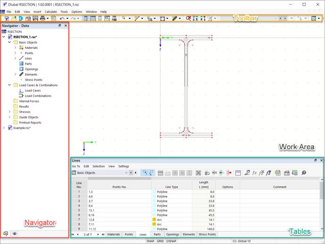
RSECTION 1 to program samodzielny do określania właściwości przekrojów zarówno dla przekrojów cienkościennych, jak i masywnych, a także do przeprowadzania analizy naprężeń. Ponadto program może być połączony zarówno z RFEM, jak i RSTAB: przekroje z programu RFEM/RSTAB są dostępne w bibliotekach programu RFEM/RSTAB, a siły wewnętrzne z programu RFEM/RSTAB można zaimportować do programu RSECTION.
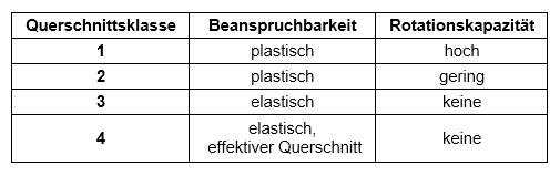
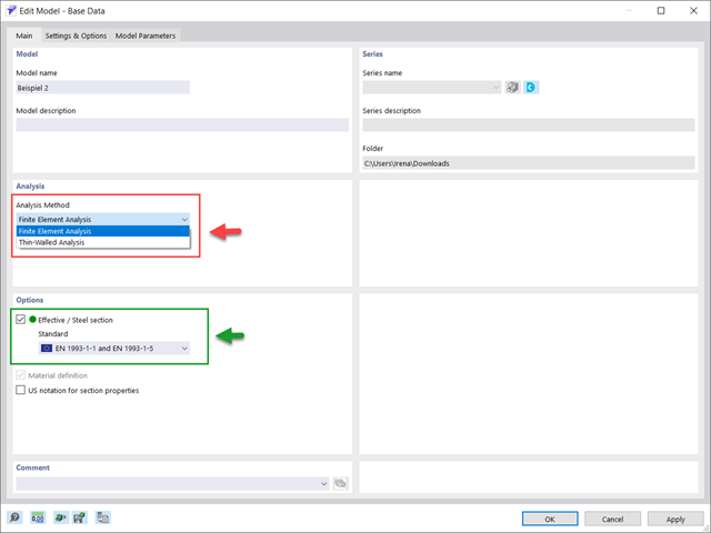
Obliczenia przekrojów zgodnie z Eurokodem 3 opierają się na klasyfikacji projektowanego przekroju według klas określonych w normie. Klasyfikacja przekrojów jest ważna, ponieważ określa granice nośności i nośności obrotowej na skutek wyboczenia lokalnego części przekroju.
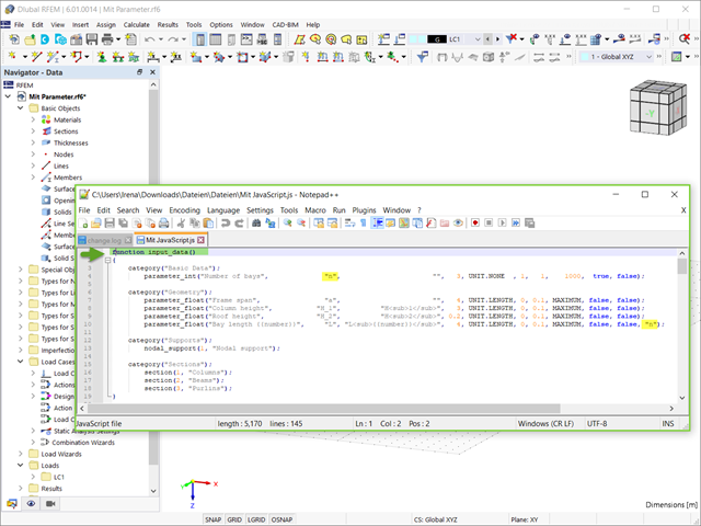
Modele konstrukcji w programie RFEM 6 można zapisywać jako bloki i wykorzystywać ponownie w innych plikach programu RFEM. Zaletą bloków dynamicznych w porównaniu z blokami nie-dynamicznymi jest to, że umożliwiają interaktywną modyfikację parametrów konstrukcyjnych w wyniku modyfikowania zmiennych wejściowych. Jednym z przykładów jest możliwość dodawania elementów konstrukcyjnych poprzez zmianę tylko liczby przęseł jako zmiennej wejściowej. W tym artykule zademonstrowano taką funkcjonalność dla bloków dynamicznych tworzonych za pomocą skryptów.
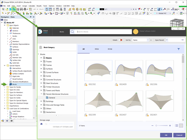
W programie RFEM 6 można zapisywać wybrane obiekty (a także całe konstrukcje) jako bloki i wykorzystywać je w innych modelach. Istnieją trzy typy bloków: bez parametrów, z parametrami i bloki dynamiczne (z wykorzystaniem JavaScript). W niniejszym artykule przedstawiono pierwszy typ bloku (bez parametrów).

Zgodnie z EN 1992-1-1 [1] belka jest prętem, którego rozpiętość jest nie mniejsza niż 3-krotna całkowita wysokość przekroju. W przeciwnym razie element konstrukcyjny należy traktować jako belkę-ścianę. Zachowanie belek-ścian (tj. belek o rozpiętości mniejszej niż 3-krotna wysokość przekroju) różni się od zachowania belek-ścian (tj. belek o rozpiętości trzykrotnie większej niż wysokość przekroju).
Projektowanie belek-ścian jest jednak często konieczne podczas analizy elementów konstrukcyjnych konstrukcji żelbetowych, ponieważ są one wykorzystywane do budowy nadproży okiennych i drzwiowych, podciągów i podciągów, połączeń między płytami dwupoziomowymi oraz konstrukcji ramowych.
Projektowanie belek-ścian jest jednak często konieczne podczas analizy elementów konstrukcyjnych konstrukcji żelbetowych, ponieważ są one wykorzystywane do budowy nadproży okiennych i drzwiowych, podciągów i podciągów, połączeń między płytami dwupoziomowymi oraz konstrukcji ramowych.
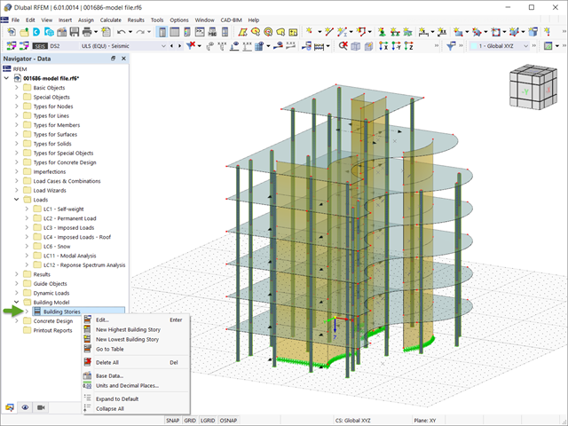
W programie RFEM 6 analizę sejsmiczną można przeprowadzić za pomocą modułów dodatkowych Analiza modalna i Analiza spektrum odpowiedzi. Zaraz po zakończeniu analizy spektralnej za pomocą rozszerzenia Model budynku można wyświetlić oddziaływania kondygnacji, przemieszczenia kondygnacji i siły w ścianach usztywniających.

Nowa generacja oprogramowania RFEM umożliwia przeprowadzanie obliczeń stateczności zbieżnych prętów drewnianych zgodnie z metodą prętów zastępczych. Zgodnie z tą metodą obliczenia można przeprowadzić, jeżeli spełnione są wytyczne normy DIN 1052, sekcja E8.4.2 dla zmiennych przekrojów. W różnych publikacjach technicznych metoda ta jest również stosowana w przypadku Eurokodu 5. W tym artykule pokazano, jak zastosować metodę prętów zastępczych dla belki dachowej o zbieżnej wysokości.
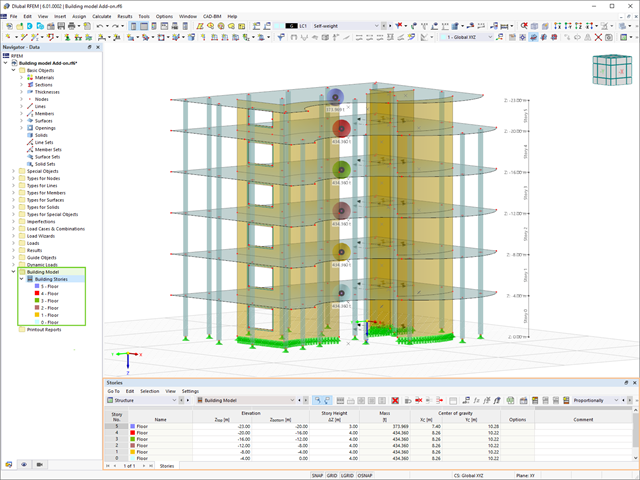
Model budynku jest jednym ze specjalnych rozszerzeń w programie RFEM 6. Jest to przydatne narzędzie do modelowania, za pomocą którego można łatwo tworzyć kondygnacje budynków i nimi manipulować. Model budynku można aktywować na początku procesu modelowania lub po jego zakończeniu.
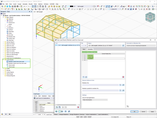
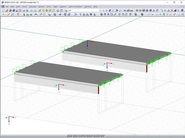
W tym artykule wyjaśniono zastosowanie powierzchni z typem sztywności "Przenoszenie obciążenia" w programie RFEM 6. Pokazano również praktyczny przykład, w którym można zademonstrować, jak na stalową halę można oddziaływać ciężarem własnym, śniegiem i wiatrem.
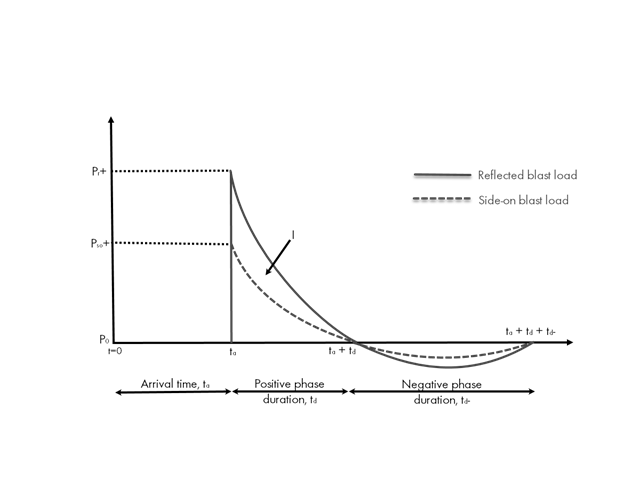
Obciążenia eksplozją od materiałów wybuchowych o dużej energii, przypadkowe lub celowe, są rzadkie, ale mogą być wymogiem projektowym. Obciążenia dynamiczne tego typu różnią się od normalnych obciążeń statycznych – są to obciążenia o znacznej wartości, ale oddziałujące bardzo krótkotrwale. Scenariusz eksplozji można przeprowadzić bezpośrednio w programie MES jako analizę historii czasowej, aby zminimalizować utratę żywotności i ocenić różne poziomy uszkodzeń konstrukcji.
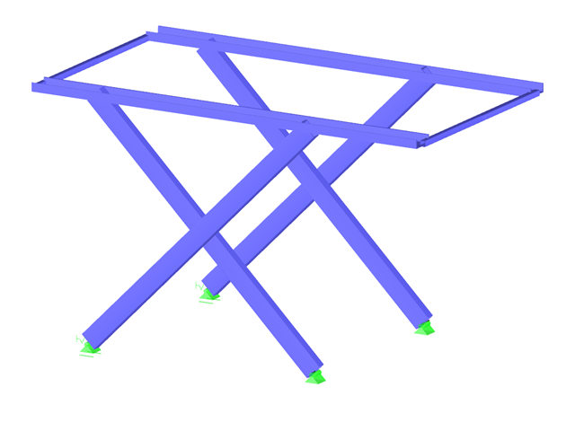
W przypadku niektórych konstrukcji konieczne jest aby zaprojektować je w różnej konfiguracji. Może się zdarzyć, że podnośnik koszowy będzie musiał być analizowany zarówno w pozycji złożonej, pół-rozłożonej, jak i w pełni rozłożonej. Ponieważ takie zadania wymagają utworzenia kilku modeli, które są prawie identyczne, możliwość aktualizacji wszystkich modeli za pomocą jednego kliknięcia myszy jest bardzo przydatna.
Za pomocą modułu dodatkowego RF-TIMBER CSA możliwe jest wymiarowanie słupów drewnianych zgodnie z kanadyjską normą O86-19. Dokładne wyznaczanie wytrzymałości na ściskanie i odpowiednich współczynników korekcyjnych dla prętów drewnianych jest istotne ze względów bezpieczeństwa. The following article will verify the factored compressive resistance in the RFEM add-on module RF-TIMBER CSA, using step-by-step analytical equations as per the CSA O86-19 standard including the column modification factors, factored compressive resistance, and final design ratio.
Zgodnie z punktem 3.2.2 normy EN 1993-1-3 możliwe jest zastosowanie podwyższonej średniej granicy plastyczności fya dla przekrojów poprzecznych tam, gdzie dochodzi do efektu dosztywnienia w wyniku powstałego odkształcenia (tzw. strain hardening).
Jeżeli żebro w stropie jest elementem konstrukcji obliczanej nieliniowo lub jest sztywno zamocowane w ścianach dochodzących, do jego modelowania należy użyć powierzchni zamiast pręta. Aby żebro nadal mogło być zaprojektowane jako element prętowy, należy zdefiniować belkę wynikową o prawidłowym mimośrodzie, która pozwala odczytać siły wewnętrzne w powłoce jako siły wewnętrzne dla równoważnego pręta.