Question:
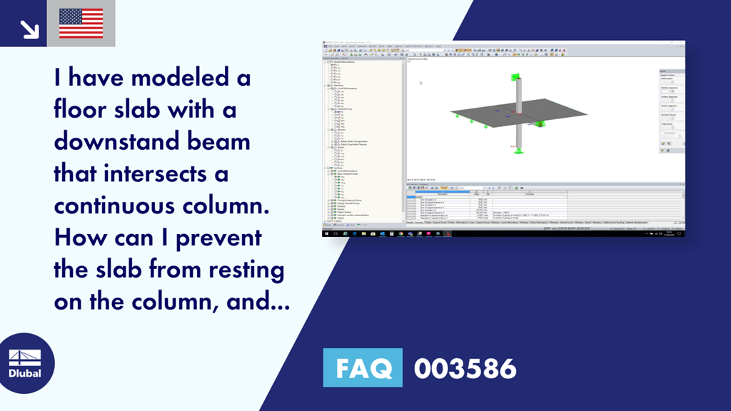
I have modeled a floor slab with a downstand beam that intersects a continuous column. How can I prevent the slab from resting on the column, and ensuring that it rests only on the downstand beam?
Answer:
To ensure that the floor only rests on the downstand beam in this situation (Image 01), we recommend modeling a minimum opening within the floor surface; see Image 02.
In order to keep the members or the lines of the members integrated into the surface, you can apply the "Connect Lines/Members" function subsequently to the entire model at once. Thus, it is ensured that the floor slab is still on the downstand beams.


Dlubal_KohlA_]_LI.jpg?mw=350&hash=ee8d38f1c4853d80307fa156c159b5e78a3fdca9)


.png?mw=600&hash=49b6a289915d28aa461360f7308b092631b1446e)
