Setting Axis System of Solid
Tips & Tricks
Each solid has a local coordinate system. The stresses and strains are also related to this local axis system.
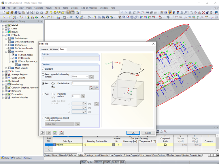
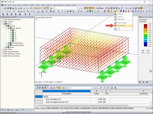
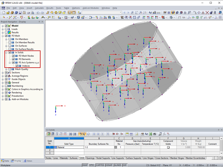
The FE axis systems can be displayed or hidden in the Project Navigator-Display using the "FE Axis System x, y, z" check box (Figure 1).
The solid coordinate system can be adjusted for solids of the Material type, provided that no layered mesh is activated for the solid (Figure 2).
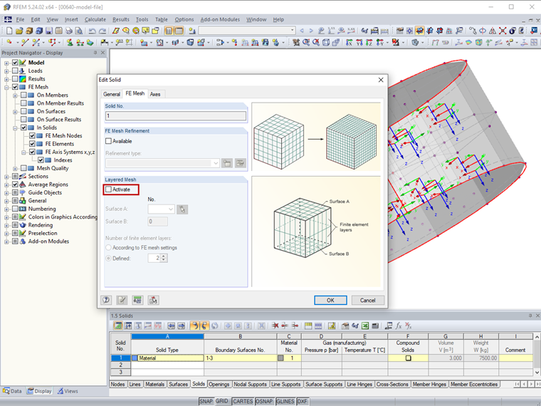
To do this, open the "Edit Solid" dialog box by double -clicking the relevant solid. The "Axes" tab manages the orientation of the local axes. In the default setting, the axes are oriented according to the global axes. The local axes x or y of the solid can also be aligned parallel to the axes of an edge surface, a line, a surface or in the direction of a user -defined coordinate system (Figure 3).
Author

Sonja von Bloh, M.Sc.
Product Engineering & Customer Support
Ms. von Bloh provides technical support for our customer and is responsible for the development of the SHAPE‑THIN program.
Keywords
Links
Write Comment...
Write Comment...
Contact us
Do you have questions or need advice?
Contact our free e-mail, chat, or forum support or find various suggested solutions and useful tips on our FAQ page.

New
Improved Cross-Section Optimization
When optimizing cross -sections in the add -on modules, you can also select any defined cross -section favorites lists - in addition to the cross -sections from the same cross -section row as the original cross -section.

SHAPE-MASSIVE | Stress analysis
- Normal stresses σx from axial force and bending
- Shear stresses τ from shear force and torsion
- Equivalent stresses σv with comparison to limit stress
- Stress ratios related to equivalent stresses
- Normal stress σx from unit normal force N
- Shear stress τ from unit shear forces Vy , Vz , Vu , Vv
- Normal stress σx from unit moments My , Mz Mu , Mv
- Is it possible to display more values for the stress distribution over the layers in RF‑LAMINATE?
- Which Dlubal Software programs can I use to calculate and design timber structures?
- I would like to design an aluminum or lightweight structure. Is it possible to use RFEM or RSTAB for this?
- Which Dlubal Software programs are required to calculate membrane and tensile structures?
- How can I model a weld, for example as a fillet weld?
- How can I additionally model welds for the connection of two surfaces with a contact solid?
- Which add-on modules and programs do I need for laminate and sandwich structures as well as cross-laminated timber (CLT)?
- I would like to analyze cable and tensile structures. Is it possible to use RFEM or RSTAB for this?
- Are the Dlubal Software programs suitable for the analysis and design of hydraulic steel structures?
- I would like to use surface releases to model a bolt connection, which can only absorb compressive stresses from the support. Unfortunately, I cannot do this because my model is always unstable. Is there a model as a template?
Associated Products