Theoretical Background
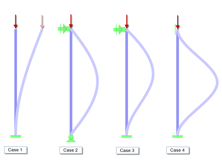
Slendernesses and the resulting reduction factors are determined using the flexural buckling analysis according to EN 1993‑1‑1, Chapter 6.3, taking into account the elastic critical buckling load Ncr. This critical load is determined analytically in the STEEL‑EC3 add‑on module using the governing effective length. For simple structures, there are four commonly used Euler cases.
In the case of complex structures, the effective length assessment is not as trivial. For this determination, you can utilize the RSBUCK add‑on module.
A critical load factor is first determined for the structure. This is multiplied by the normal forces of the members to obtain the critical loads. The corresponding effective lengths for buckling around both axes are calculated using the adjusted formula: Ncr = E ∙ I ∙ π² / Lcr. Finally, the effective load factors are determined from this relation: kcr = Lcr / L.
Global and Local Mode Shapes in RSBUCK
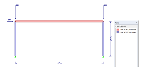
The determination of mode shapes and the proper evaluation are explained with the following example of a simple frame.
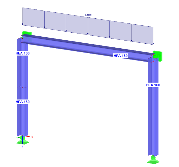
The load plays an important role in determining a buckling mode and buckling lengths: Buckling values depend not only on the structural model, but also on the relation of normal forces to the total critical buckling load Ncr. Effective lengths can be calculated only for members with compressive forces. In addition, the load distribution over the entire structure affects the determination of the critical factors. By evaluating the individual mode shapes graphically, you can identify whether there is a global or a local mode shape. If there is a critical load of an individual member in the case of the most unfavorable structural critical load, this will be apparent in the graphic. In the case of such a failure, the results cannot be used for all other members and must not be evaluated.
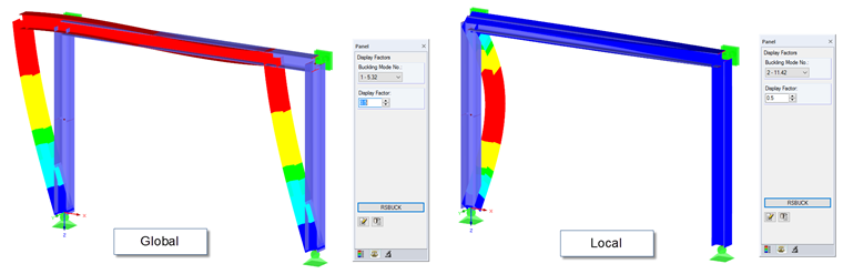
In our example, the first mode shape with the critical load factor of 5.32 illustrates the global displacement of the frame in the frame plane. The second mode shape, with the critical load factor of 11.42, illustrates the local displacement of the left column in the frame plane (buckling around the minor axis z).
Divided Members
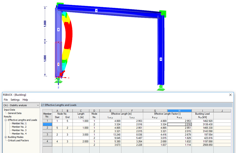
When calculating the effective lengths and effective length factors, you have to consider the division of members. In this example, the left column of the frame consists of two single members. For technical modeling reasons, the column was divided in the middle. When considering the local mode shape (Buckling Mode No. 2), this can be categorized under Euler case No. 2 and the expected result of the effective length factor kcr,z = 1.0. However, Result Window 2.1 in the add‑on module displays the effective length factor kcr,z = 2.0 for both "partial" members of the column.
This can be explained easily by the relations mentioned above, under "Theoretical Background". In this case, the buckling length for the entire column is equal to the column length; therefore, the effective length factor is 1. However, since single members are evaluated in RSBUCK, kcr = Lcr / L where L = 0.5 ⋅ column length results in an effective length factor of 2.0.
The effective length factors for continuous members cannot be determined directly in RSBUCK. To do this, you can evaluate the results of the individual members. The member that proves the smallest buckling load Ncr can be considered as the governing single member for a continuous member. You can then calculate the kcr values from the effective length of this member and the total length of the continuous member.


.png?mw=350&hash=fe72c46b04993d960fc1b58d5270301861f6f9e5)


.png?mw=600&hash=49b6a289915d28aa461360f7308b092631b1446e)
