During the plausibility check, I get an error message saying that the surface opposite from the contact surface cannot be located. How can I solve this?
Answer
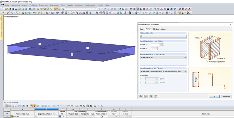
When modeling a contact solid, it is necessary to pay attention to the parallel arrangement of both contact surfaces and the identical design, among other things.
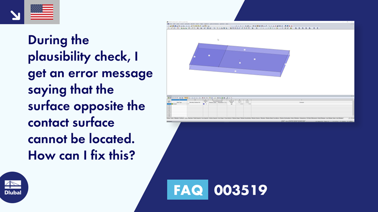
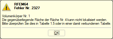
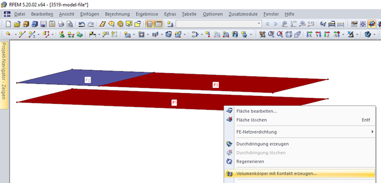
In Figure 01, a contact solid with the contact between the top and bottom surface should be created. The top contact surface is divided into two surfaces S2 and S3, and thus does not correspond to the bottom contact surface S1. Therefore, the error message shown in Figure 02 appears. In this case, it is necessary to define two contact solids. The contact solids can be created, for example, by using the "Create Solid with Contact" feature. To do this, select the contact surfaces and open the corresponding function in the shortcut menu; as an alternative, it is possible to create the contact solid manually. Watch the FAQ explanatory video to see both procedures.
Keywords
Contact solid Contact surface Error No. 2327 Opposite surface
Downloads
Contact us
Did you find your question?
If not, contact us via our free e-mail, chat, or forum support, or send us your question via the online form.
Recommended Events
Eurocode 5 | Timber structures according to EN 1995-1-1
Online Training 17 March 2021 8:30 AM - 12:30 PM CET
Eurocode 3 | Steel structures according to DIN EN 1993-1-1
Online Training 18 March 2021 8:30 AM - 12:30 PM CET
Eurocode 3 | Steel structures according to DIN EN 1993-1-1
Online Training 6 May 2021 8:30 AM - 12:30 PM
Eurocode 2 | Concrete structures according to DIN EN 1992-1-1
Online Training 11 May 2021 8:30 AM - 12:30 PM
Eurocode 5 | Timber structures according to DIN EN 1995-1-1
Online Training 20 May 2021 8:30 AM - 12:30 PM
RFEM | Structural dynamics and earthquake design according to EC 8
Online Training 2 June 2021 8:30 AM - 12:30 PM
Stability Design in Steel Construction with RFEM and RSTAB
Webinar 1 December 2020 2:00 PM - 2:45 PM CET
Videos
KB 000605 | Setting the Concrete Cover in RF-/FOUNDATION Pro According to EN 1992-1-1
Length 0:32 min
[PL] CP 001184 | "Terma Bania" Building Extension and Renovation in Białka Tatrzańska, Poland
Length 0:06 min
Models to Download
Knowledge Base Articles

New
For relatively large or relatively small surfaces, it can happen that the automatically created result values do not fit the model: In case of large surfaces, there can be too much result values, in case of small surfaces, too few.Screenshots
Product Features Articles

New
Increased Calculation Performance by Reducing the Nodal Degrees of Freedom
The number of degrees of freedom in a node is no longer a global calculation parameter in RFEM (6 degrees of freedom for each mesh node in 3D models, 7 degrees of freedom for the warping torsion analysis). Thus, each node is generally considered with a different number of degrees of freedom, which leads to a variable number of equations in the calculation.
This modification speeds up the calculation, especially for models where a significant reduction of the system could be achieved (e.g. trusses and membrane structures).
Frequently Asked Questions (FAQ)
- How are the signs for the release results of a line release and line hinges interpreted?
- Why is the deflection of the reinforced concrete floor sometimes greater when selecting a larger basic reinforcement?
- Is it possible to use an average region in the result from contact stress?
- I would like to calculate and design "temporary structures." What do I need for this?
- Which programs can I use to calculate and design power plants?
- In the filter settings for the values on surfaces, you can display a certain range of results and hide the rest. How can I hide a certain range of values and display the rest?
- What is the best way to consider steel fiber reinforced concrete with the structural analysis program RFEM?
- How is the position of the additional reinforcement considered in RF‑CONCRETE Surfaces when determining hc,ef?
- I would expect the results from my load combination (CO) set to a linear analysis to equal the summation of the results from my load cases (LC) also set to a linear analysis. Why do the results not match?
- Which Dlubal Software programs are required to calculate membrane and tensile structures?
Customer Projects