47 Wyniki
Wyświetl wyniki:
Sortuj według:

Analiza wyboczenia giętnego jest połączeniem analizy stateczności i stanu granicznego nośności, stosowana w konstrukcjach stalowych od setek lat. Punktem wyjścia do rozważenia kwestii stateczności jest krytyczne obciążenie wyboczeniowe, ale dotychczas nie przeprowadzono obliczeń bez uwzględnienia imperfekcji. Jak dokładnie określane są te imperfekcje?

W artykule przedstawiono równania wykorzystywane przez program do określenia podpór podporowych na podstawie parametrów słupa.

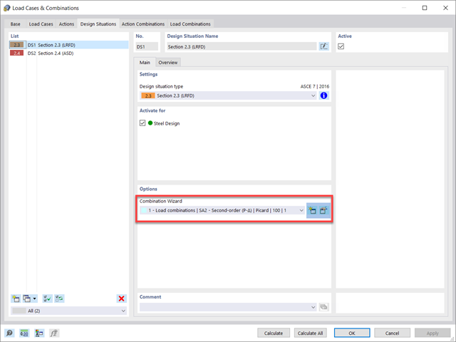
Norma ASCE 7-22 [1], rozdz. 12.9.1.6 określa, kiedy efekty P-delta powinny być uwzględniane podczas przeprowadzania analizy modalnego spektrum odpowiedzi dla obliczeń sejsmicznych. W NBC 2020 [2], Wys. 4.1.8.3.8.c jedynie w niewielkim stopniu wymaga uwzględnienia przechyłów spowodowanych interakcją obciążeń grawitacyjnych z konstrukcją odkształconą. Z tego względu podczas przeprowadzania analizy sejsmicznej mogą wystąpić sytuacje, w których efekty drugiego rzędu, znane również jako P-delta, muszą zostać uwzględnione.

W rozszerzeniu Projektowanie konstrukcji stalowych dla programu RFEM 6 dostępne są trzy typy ram sprężystych (zwykłe, pośrednie i specjalne). Wyniki obliczeń sejsmicznych zgodnie z AISC 341-22 są podzielone na dwie sekcje: wymagania dotyczące prętów i połączeń.

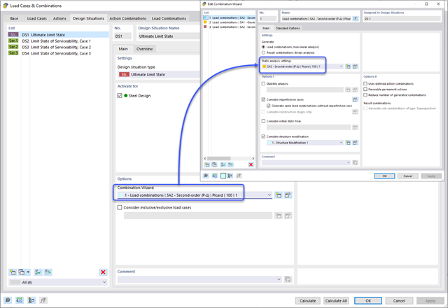
Aby ocenić, czy w obliczeniach dynamicznych konieczne jest również uwzględnienie analizy drugiego rzędu, w normie EN 1998‑1, sekcje 2.2.2 i 4.4.2.2 zawarto współczynnik wrażliwości międzykondygnacyjnego znoszenia θ. Można ją obliczyć i przeanalizować za pomocą programów RFEM 6 i RSTAB 9.
Zgodnie z normami EN 1998-1 sekcje 2.2.2 i 4.4.2.2 do obliczeń stanu granicznego nośności należy przeprowadzić obliczenia z uwzględnieniem teorii drugiego rzędu (efekt P-Δ). Efekt ten nie musi być uwzględniany tylko w przypadku, gdy współczynnik wrażliwości międzykondygnacyjnej jest mniejszy niż 0,1.

W rozszerzeniu Projektowanie konstrukcji stalowych dla programu RFEM 6 dostępne są trzy typy ram sprężystych (zwykłe, pośrednie i specjalne). Wyniki obliczeń sejsmicznych zgodnie z AISC 341-16 są podzielone na dwie sekcje: wymagania dotyczące prętów i połączeń.
Stworzenie przykładu walidacyjnego dla obliczeniowej mechaniki płynów (CFD) jest kluczowym krokiem w zapewnieniu dokładności i wiarygodności wyników symulacji. This process involves comparing the outcomes of CFD simulations with experimental or analytical data from real-world scenarios. The objective is to establish that the CFD model can faithfully replicate the physical phenomena it is intended to simulate.
Blachownica to ekonomiczny wybór w przypadku konstrukcji o dużych rozpiętościach. I-section steel plate girder typically has a deep web to maximize its shear capacity and flange separation, yet thin web to minimize the self-weight. Due to its large height-to-thickness (h/tw) ratio, transverse stiffeners may be required to stiffen the slender web.
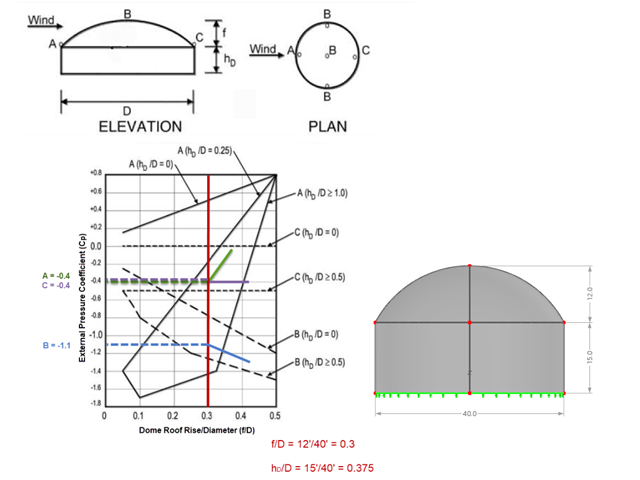
Jeśli chodzi o obciążenia wiatrem konstrukcje budowlane zgodnie z ASCE 7, można znaleźć wiele źródeł, które mogą uzupełnić normy projektowe i pomóc inżynierom w zastosowaniu obciążeń poprzecznych. Jednak inżynierom może być trudniej znaleźć podobne zasoby dla obciążeń wiatrem na konstrukcjach innych niż budynki. W tym artykule omówiono etapy obliczania i przykładania obciążeń wiatrem zgodnie z ASCE 7-22 na okrągłym zbiorniku żelbetowym z dachem w kształcie kopuły.

Zarówno analiza drgań własnych, jak i analiza spektrum odpowiedzi przeprowadzane są na układzie liniowym. Jeżeli w modelu występują nieliniowości, podlega on linearyzacji, dzięki czemu elementy nieliniowe nie są brane pod uwagę w dalszej analizie. Mogą to być na przykład pręty rozciągane, podpory nieliniowe lub przeguby nieliniowe. W tym artykule pokazano, w jaki sposób można nimi zarządzać w analizie dynamicznej.
Analiza spektrum odpowiedzi jest jedną z najczęściej stosowanych metod obliczeniowych w przypadku obciążenia trzęsieniem ziemi. Metoda ta ma wiele zalet, a najważniejsza z nich to możliwość znacznego uproszczenia obliczeń. Skomplikowany charakter obciążenia jakim jest trzęsienie ziemi jest upraszczany do postaci, która umożliwia przeprowadzenie analizy o rozsądnym stopniu pracochłonności. Wadą metody jest natomiast to, że w wyniku tego uproszczenia traci się część informacji o obciążeniu. Sposobem na zniwelowanie tego ograniczenia może być zastosowanie równoważnej kombinacji liniowej podczas łączenia odpowiedzi modalnych. W poniższym artykule wyjaśniono to bardziej szczegółowo na konkretnym przykładzie.
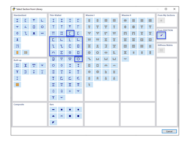
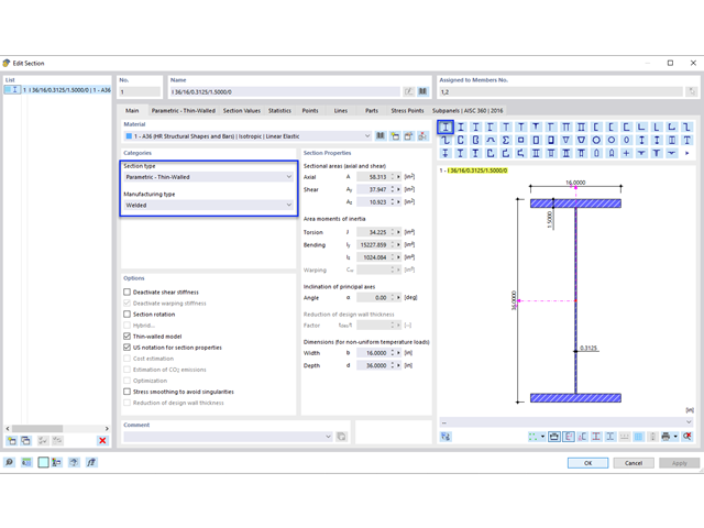
W obliczeniach konstrukcji stalowych formowanych na zimno często wymagane są niestandardowe przekroje. In RFEM 6, the custom section can be created using one of the “Thin-Walled” sections available in the library. For other sections that do not meet any of the 14 available cold-formed shapes, the sections can be created and imported from the standalone program, RSECTION. For general information on AISI steel design in RFEM 6, refer to the Knowledge Base article provided at the end of the page.
Metoda CSA S16:19 Skutki stateczności w analizie sprężystej w Załączniku O.2 stanowi alternatywę dla metody Uproszczonej analizy stateczności z punktu 8.4.3. W tym artykule zostaną opisane wymagania załącznika O.2 i zastosowania w RFEM 6.

Wymiarowanie prętów stalowych formowanych na zimno zgodnie z AISI S100-16 jest teraz dostępne w programie RFEM 6. Design can be accessed by selecting “AISC 360” as the standard in the Steel Design add-on. “AISI S100” is then automatically selected for the cold-formed design (Image 01).
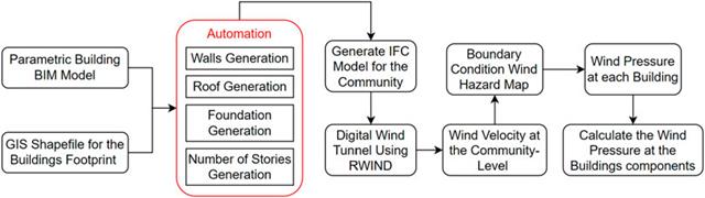
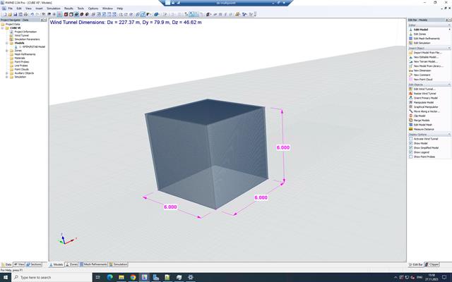
W artykule tym opracowano nowatorskie podejście do generowania modeli CFD na poziomie miejscowości poprzez połączenie modelowania informacji o budynku (BIM) i systemów informacji geograficznej (GIS) w celu zautomatyzowania generowania trójwymiarowego modelu terenu o wysokiej rozdzielczości, który zostanie wykorzystany jako dane wejściowe dla cyfrowego tunelu aerodynamicznego z wykorzystaniem RWIND.
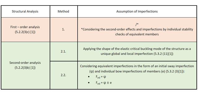
W tym artykule w Bazie informacji omówiono różne metody analizy stateczności opisane w normie EN 1993-1-1:2005 i ich zastosowanie w programie RFEM 6.
Samodzielny program RSECTION określa właściwości przekrojów cienkościennych i masywnych oraz przeprowadza analizę naprężeń. W poprzednim artykule z Bazy wiedzy zatytułowanym "Graficzne/tabelaryczne tworzenie przekrojów zdefiniowanych przez użytkownika w PRZEKRÓJ 1" omówiono podstawy definiowania przekrojów w programie. Z drugiej strony, ten artykuł jest podsumowaniem sposobu określania właściwości przekroju i przeprowadzania analizy naprężeń.
Wraz z programami do analizy statyczno-wytrzymałościowej RFEM 6, RSTAB 9, RSECTION 1 i RWIND 2, Dlubal Software przedstawia nową generację programów do analizy statyczno-wytrzymałościowej. Getreu dem Motto „Statik, die Spaß macht…“ werden den Anwendern universelle Werkzeuge in die Hand gegeben, mit denen alle Anforderungen in der Tragwerksplanung bewältigt werden können. Was sich sonst noch bei Dlubal Software Neues getan hat, erfahren Sie in diesem Artikel.
Norma dotycząca konstrukcji stalowych AISC 360-16 wymaga uwzględnienia stateczności konstrukcji jako całości oraz każdego z jej elementów. Dostępne są różne metody, w tym metoda bezpośredniego uwzględnienia w analizie, metoda długości efektywnej i metoda analizy bezpośredniej. W tym artykule podkreślono ważne wymagania rozdz. C oraz metodę bezpośredniej analizy, która zostanie uwzględniona w modelu konstrukcji stalowej wraz z zastosowaniem w programie RFEM 6.
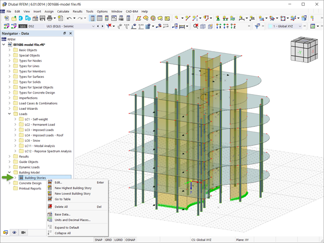
W programie RFEM 6 analizę sejsmiczną można przeprowadzić za pomocą modułów dodatkowych Analiza modalna i Analiza spektrum odpowiedzi. Zaraz po zakończeniu analizy spektralnej za pomocą rozszerzenia Model budynku można wyświetlić oddziaływania kondygnacji, przemieszczenia kondygnacji i siły w ścianach usztywniających.

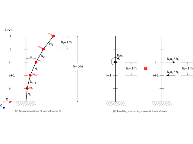
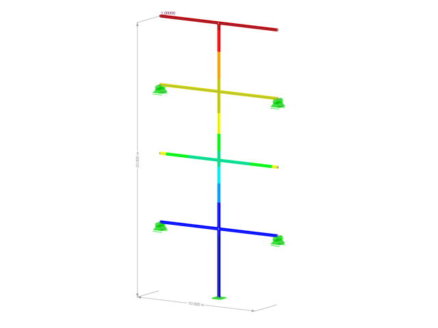
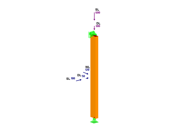
Sprawdzenie stateczności dla wymiarowania prętów zastępczych zgodnie z EN 1993-1-1, AISC 360, CSA S16 i innymi normami międzynarodowymi wymaga uwzględnienia długości obliczeniowej (tj. efektywnej długości prętów). W programie RFEM 6 długość efektywną można określić ręcznie, przypisując podpory węzłowe i współczynniki długości efektywnej lub, z drugiej strony, poprzez import z analizy stateczności. Obie opcje zostaną przedstawione w tym artykule poprzez określenie efektywnej długości słupa obramowanego na rysunku 1.

W tym artykule technicznym omówimy podstawowe kwestie dotyczące korzystania z rozszerzenia Skręcanie skrępowane (7 stopni swobody). Jest ono w pełni zintegrowane z programem głównym i umożliwia uwzględnienie deplanacji przekroju podczas obliczania elementów prętowych. W połączeniu z rozszerzeniami Analiza stateczności oraz Wymiarowanie stali, możliwe jest przeprowadzenie obliczeń wyboczenia giętno-skrętnego z siłami wewnętrznymi zgodnie z analizą drugiego rzędu oraz uwzględnieniem imperfekcji.
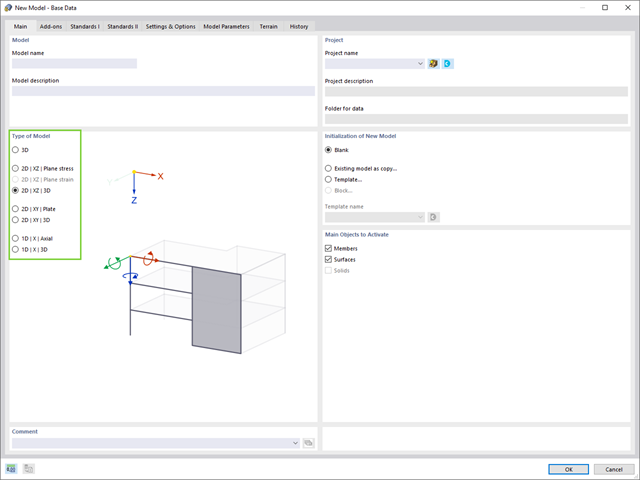
W rzeczywistości konstrukcje są trójwymiarowe, można je jednak uprościć i przeanalizować jako modele 2D lub 1D. Typ modelu ma decydujący wpływ na sposób naprężenia elementów konstrukcyjnych i należy go zdefiniować przed modelowaniem i obliczeniami.
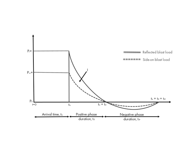
Obciążenia eksplozją od materiałów wybuchowych o dużej energii, przypadkowe lub celowe, są rzadkie, ale mogą być wymogiem projektowym. Obciążenia dynamiczne tego typu różnią się od normalnych obciążeń statycznych – są to obciążenia o znacznej wartości, ale oddziałujące bardzo krótkotrwale. Scenariusz eksplozji można przeprowadzić bezpośrednio w programie MES jako analizę historii czasowej, aby zminimalizować utratę żywotności i ocenić różne poziomy uszkodzeń konstrukcji.
W tym artykule, przy użyciu modułu dodatkowego RF-/TIMBER AWC, sprawdzono adekwatność drewna o wymiarach 2x4 poddanego łącznemu zginaniu dwukierunkowemu i ściskaniu osiowemu. Właściwości i obciążenia belki i słupa podano na podstawie przykładu E1.8 z AWC Structural Wood Design Example 2015/2018.
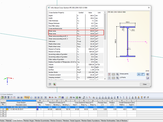
Właściwości przekrojów w RFEM i RSTAB uwzględniają różne typy powierzchni ścinania. W tym artykule technicznym wyjaśniono sposób obliczania i znaczenie różnych wartości.
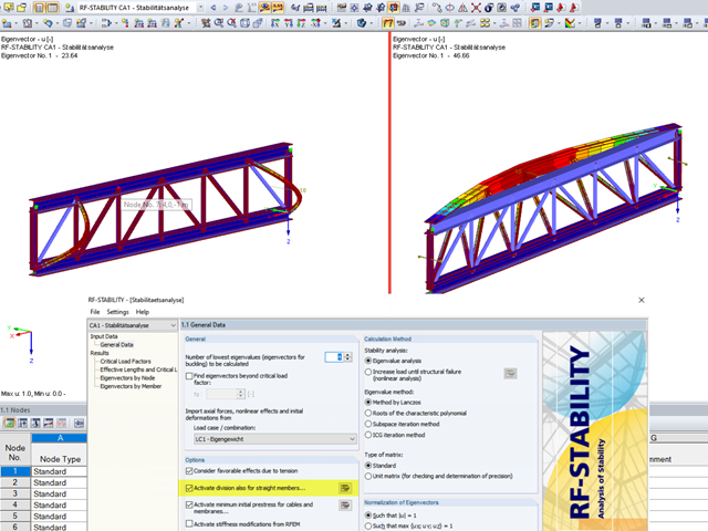
Bei der statischen Analyse stabilitätsgefährdeter Bauteile mit den Modulen RF-STABIL (für RFEM) beziehungsweise RSKNICK (für RSTAB) kann eine Aktivierung der internen Teilung von Stäben erforderlich werden.
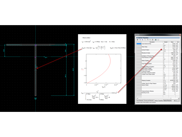
Mit dem Querschnittsprogramm DUENQ können beliebige dünnwandige Querschnitte erstellt und anschließend auch in RFEM oder RSTAB als Stabquerschnitt verwendet werden. Dabei kann DUENQ von beliebigen Querschnitten alle relevanten Querschnittswerte für eine Bemessung und Spannungsanalyse ausgeben.
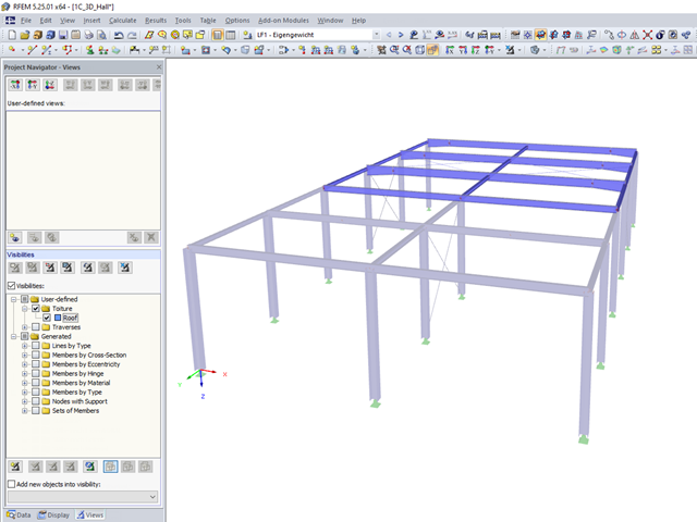
Benutzerdefinierte Sichtbarkeiten erleichtern das Programmhandling. Einmal erstellt, können schnell beliebige Modellgruppen aus- bzw. eingeblendet werden. Dies erleichtert u.a. die Analyse der Ergebnisse in größeren 3D Strukturen aber auch die Erstellung des Protokolls. Bei Änderungen der Geometrie müssen die bestehenden Sichtbarkeiten unter Umständen aktualisiert werden.