39 Wyniki
Wyświetl wyniki:
Sortuj według:

Ocena przemieszczenia kondygnacji w budynku jest kluczowa dla zapewnienia zadowalających parametrów konstrukcyjnych poprzez ograniczenie przemieszczenia kondygnacji. Nadmierne znoszenie może powodować niestateczność systemu i powodować uszkodzenia elementów niekonstrukcyjnych, takich jak ściany działowe. W tym artykule opisano procedurę wyznaczania przemieszczeń międzykondygnacyjnych zgodnie z ASCE 7-22 i rozszerzeniem Model budynku w programie RFEM 6.

Blachownica to ekonomiczny wybór w przypadku konstrukcji o dużych rozpiętościach. I-section steel plate girder typically has a deep web to maximize its shear capacity and flange separation, yet thin web to minimize the self-weight. Due to its large height-to-thickness (h/tw) ratio, transverse stiffeners may be required to stiffen the slender web.

Wyboczenie giętno-skrętne (LTB) jest zjawiskiem, które występuje, gdy belka lub element konstrukcyjny są zginane, a pas ściskany nie jest wystarczająco podparty bocznie. Prowadzi to do kombinacji przemieszczenia bocznego i skręcenia. Jest to decydujący czynnik przy wymiarowaniu elementów konstrukcyjnych, zwłaszcza smukłych belek i dźwigarów.

W rozszerzeniu Projektowanie konstrukcji stalowych dla programu RFEM 6 dostępne są trzy typy ram sprężystych (zwykłe, pośrednie i specjalne). Wyniki obliczeń sejsmicznych zgodnie z AISC 341-22 są podzielone na dwie sekcje: wymagania dotyczące prętów i połączeń.

Rozszerzenie Projektowanie konstrukcji stalowych w RFEM 6 oferuje teraz możliwość przeprowadzania obliczeń sejsmicznych zgodnie z AISC 341-16 i AISC 341-22. Obecnie dostępnych jest pięć typów systemów sejsmicznych (SFRS).

W rozszerzeniu Projektowanie konstrukcji stalowych dla programu RFEM 6 dostępne są trzy typy ram sprężystych (zwykłe, pośrednie i specjalne). Wyniki obliczeń sejsmicznych zgodnie z AISC 341-16 są podzielone na dwie sekcje: wymagania dotyczące prętów i połączeń.

Obliczanie ramy momentowej zgodnie z AISC 341-16 jest teraz możliwe w rozszerzeniu Projektowanie konstrukcji stalowych dla programu RFEM 6. Wynik obliczeń sejsmicznych jest podzielony na dwie sekcje: wymagania dotyczące prętów i połączeń. W tym artykule omówiono wymaganą wytrzymałość połączenia. Przedstawiono przykładowe porównanie wyników pomiędzy RFEM a AISC Seismic Design Manual.

Obliczenia zwykłej ramy stężonej koncentrycznie (OCBF) oraz SCBF (specjalnej konstrukcji szkieletowej stężonej koncentrycznie) można przeprowadzić w rozszerzeniu Projektowanie konstrukcji stalowych dla programu RFEM 6. Wyniki obliczeń sejsmicznych zgodnie z AISC 341-16 i 341-22 są podzielone na dwie sekcje: Wymagania dotyczące prętów i połączeń.
Blachownica to ekonomiczny wybór w przypadku konstrukcji o dużych rozpiętościach. I-section steel plate girder typically has a deep web to maximize its shear capacity and flange separation, yet thin web to minimize the self-weight. Due to its large height-to-thickness (h/tw) ratio, transverse stiffeners may be required to stiffen the slender web.
W przypadku analizy stateczności prętów przy użyciu metody pręta zastępczego konieczne jest zdefiniowanie długości wyboczeniowej lub zwichrzenia w celu określenia obciążenia krytycznego dla utraty stateczności. W tym artykule przedstawiono funkcję specyficzną dla programu RFEM 6, za pomocą której można przypisać mimośród do podpór węzłowych, a tym samym wpłynąć na określenie krytycznego momentu zginającego uwzględnianego w analizie stateczności.
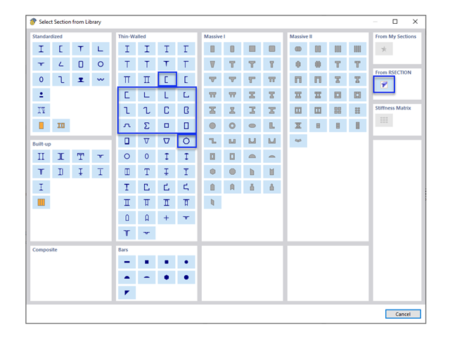
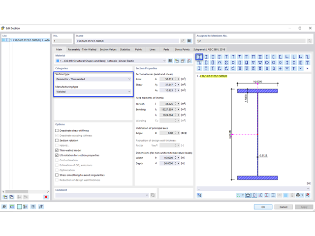
W obliczeniach konstrukcji stalowych formowanych na zimno często wymagane są niestandardowe przekroje. In RFEM 6, the custom section can be created using one of the “Thin-Walled” sections available in the library. For other sections that do not meet any of the 14 available cold-formed shapes, the sections can be created and imported from the standalone program, RSECTION. For general information on AISI steel design in RFEM 6, refer to the Knowledge Base article provided at the end of the page.
Metoda CSA S16:19 Skutki stateczności w analizie sprężystej w Załączniku O.2 stanowi alternatywę dla metody Uproszczonej analizy stateczności z punktu 8.4.3. W tym artykule zostaną opisane wymagania załącznika O.2 i zastosowania w RFEM 6.

Wymiarowanie prętów stalowych formowanych na zimno zgodnie z AISI S100-16 jest teraz dostępne w programie RFEM 6. Design can be accessed by selecting “AISC 360” as the standard in the Steel Design add-on. “AISI S100” is then automatically selected for the cold-formed design (Image 01).
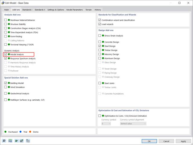
Rozszerzenie „Analiza modalna” w RFEM 6 umożliwia przeprowadzanie analizy modalnej układów konstrukcyjnych, określając w ten sposób wartości drgań własnych, takie jak częstotliwości drgań własnych, kształty modalne, masy modalne i efektywne modalne współczynniki masy. Wyniki te można wykorzystać do obliczeń drgań, a także do dalszych analiz dynamicznych (na przykład obciążenia widmem odpowiedzi).
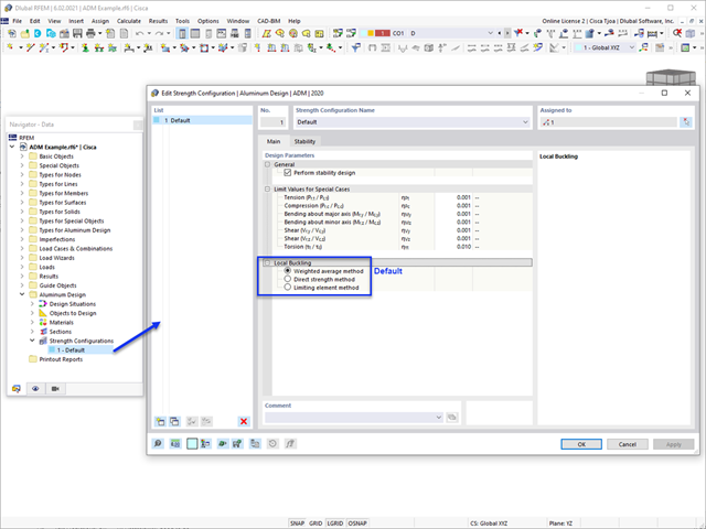
W tym artykule omówiono dostępne opcje określania nominalnej wytrzymałości na zginanie Mnlb dla stanu granicznego wyboczenia lokalnego, podczas projektowania zgodnie z Aluminium Design Manual (Podręcznik projektowania konstrukcji aluminiowych 2020).
Samodzielny program RSECTION określa właściwości przekrojów cienkościennych i masywnych oraz przeprowadza analizę naprężeń. W poprzednim artykule z Bazy wiedzy zatytułowanym "Graficzne/tabelaryczne tworzenie przekrojów zdefiniowanych przez użytkownika w PRZEKRÓJ 1" omówiono podstawy definiowania przekrojów w programie. Z drugiej strony, ten artykuł jest podsumowaniem sposobu określania właściwości przekroju i przeprowadzania analizy naprężeń.

Analiza modalna jest punktem wyjścia do analizy dynamicznej układów konstrukcyjnych. Można ją wykorzystać do określenia wartości drgań własnych, takich jak częstotliwości drgań własnych, kształty drgań własnych, masy modalne i efektywne współczynniki masy modalnej. Wynik ten może zostać wykorzystany do obliczeń drgań oraz do dalszych analiz dynamicznych (na przykład obciążenia widmem odpowiedzi).

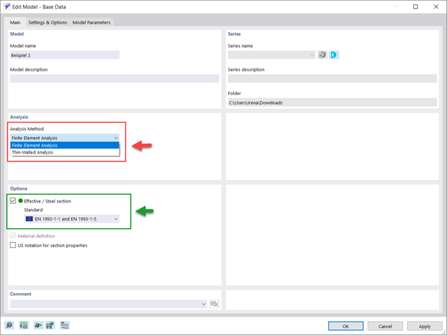
Jakość analizy statyczno-wytrzymałościowej budynków jest dużo lepsza, gdy można uwzględnić warunki gruntowe w sposób możliwie najbardziej realistyczny. W programie RFEM 6 można realistycznie określić kontur glebowy do analizy za pomocą rozszerzenia Analiza geotechniczna. Ten dodatek można aktywować w danych bazowych modelu, jak pokazano na rysunku 01.

Rozszerzenie Wymiarowanie betonu umożliwia wymiarowanie słupów betonowych zgodnie z ACI 318-19. Poniższy artykuł potwierdzi wymiarowanie zbrojenia w rozszerzeniu Wymiarowanie betonu przy użyciu równań analitycznych krok po kroku zgodnie z normą ACI 318-19, w tym wymagane zbrojenie podłużne, pole przekroju brutto i rozmiar/rozstaw ściągu.

Dzięki rozszerzeniu Połączenia stalowe dla RFEM 6 można tworzyć i analizować połączenia stalowe przy użyciu wydzielonego modelu ES. Modelowanie połączeń można kontrolować poprzez proste i wygodne wprowadzanie elementów. Elementy stalowego połączenia można definiować ręcznie lub przy użyciu szablonów dostępnych w bibliotece. Pierwsza metoda została opisana w poprzednim artykule z Bazy wiedzy zatytułowanym „Nowe podejście do wymiarowania połączeń stalowych w programie RFEM 6”. W tym artykule skupimy się na tej drugiej metodzie; tzn. pokaże, jak definiować komponenty połączenia stalowego przy użyciu szablonów dostępnych w bibliotece programu.
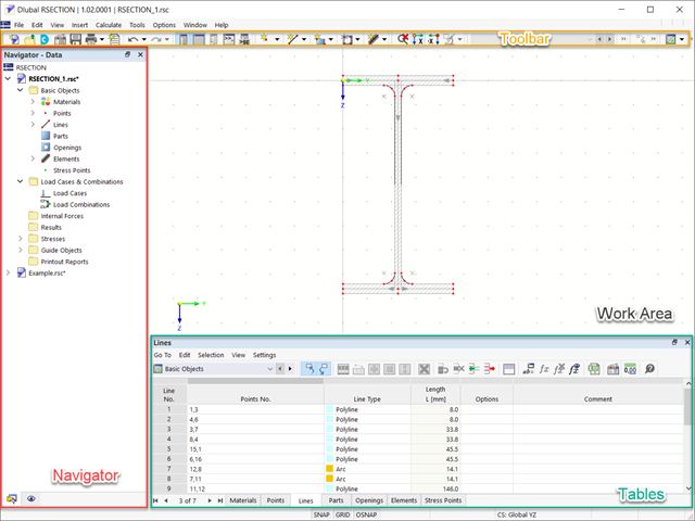
RSECTION 1 to program samodzielny do określania właściwości przekrojów zarówno dla przekrojów cienkościennych, jak i masywnych, a także do przeprowadzania analizy naprężeń. Ponadto program może być połączony zarówno z RFEM, jak i RSTAB: przekroje z programu RFEM/RSTAB są dostępne w bibliotekach programu RFEM/RSTAB, a siły wewnętrzne z programu RFEM/RSTAB można zaimportować do programu RSECTION.

Rozszerzenie Projektowanie konstrukcji aluminiowych dla RFEM 6 wymiaruje pręty aluminiowe ze względu na stan graniczny nośności i użytkowalności zgodnie z Eurokodem 9. Ponadto możliwe jest wymiarowanie zgodnie z ADM 2020 (norma amerykańska).
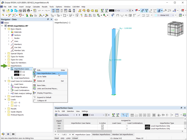
Imperfekcje w inżynierii konstrukcyjnej to odchylenia elementów konstrukcyjnych od ich idealnego kształtu, powstałe podczas produkcji. Są one często wykorzystywane w obliczeniach w celu określenia równowagi sił w elementach konstrukcyjnych w układzie odkształconym.
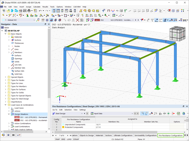
Stal ma słabe właściwości termiczne pod względem ognioodporności. Rozszerzalność termiczna dla wzrastającej temperatury jest bardzo duża w porównaniu z rozszerzalnością innych materiałów budowlanych i może powodować efekty, których nie byłoby w obliczeniach w normalnej temperaturze ze względu na utwierdzenie elementu. Wraz ze wzrostem temperatury wzrasta ciągliwość stali, a jej wytrzymałość maleje. Ponieważ stal traci 50% swojej wytrzymałości w temperaturze 600 °C, ważne jest, aby chronić elementy przed skutkami pożaru. W przypadku zabezpieczonych elementów stalowych, dzięki lepszej reakcji termicznej można wydłużyć ognioodporność.

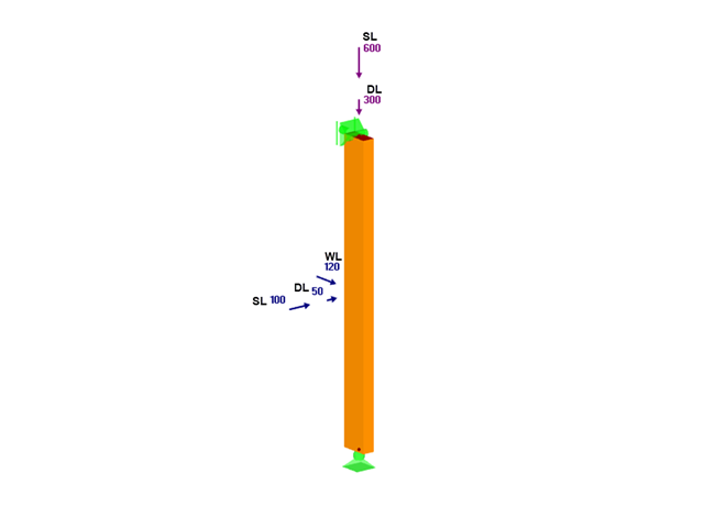
Sprawdzenie stateczności dla wymiarowania prętów zastępczych zgodnie z EN 1993-1-1, AISC 360, CSA S16 i innymi normami międzynarodowymi wymaga uwzględnienia długości obliczeniowej (tj. efektywnej długości prętów). W programie RFEM 6 długość efektywną można określić ręcznie, przypisując podpory węzłowe i współczynniki długości efektywnej lub, z drugiej strony, poprzez import z analizy stateczności. Obie opcje zostaną przedstawione w tym artykule poprzez określenie efektywnej długości słupa obramowanego na rysunku 1.

Obliczenia konstrukcji złożonych za pomocą oprogramowania do analizy elementów skończonych są zazwyczaj przeprowadzane na całym modelu. Jednak wznoszenie tego typu konstrukcji jest procesem wieloetapowym, w którym ostateczny stan konstrukcji uzyskuje się poprzez połączenie poszczególnych elementów konstrukcyjnych. Aby uniknąć błędów w obliczeniach ogólnych modeli, należy wziąć pod uwagę wpływ procesu konstrukcyjnego. W programie RFEM 6 jest to możliwe za pomocą rozszerzenia Analiza etapów budowy (CSA).
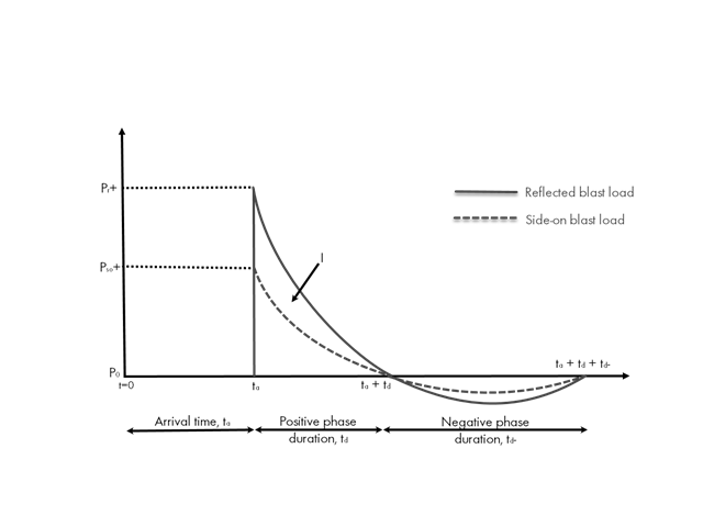
Obciążenia eksplozją od materiałów wybuchowych o dużej energii, przypadkowe lub celowe, są rzadkie, ale mogą być wymogiem projektowym. Obciążenia dynamiczne tego typu różnią się od normalnych obciążeń statycznych – są to obciążenia o znacznej wartości, ale oddziałujące bardzo krótkotrwale. Scenariusz eksplozji można przeprowadzić bezpośrednio w programie MES jako analizę historii czasowej, aby zminimalizować utratę żywotności i ocenić różne poziomy uszkodzeń konstrukcji.
W tym artykule, przy użyciu modułu dodatkowego RF-/TIMBER AWC, sprawdzono adekwatność drewna o wymiarach 2x4 poddanego łącznemu zginaniu dwukierunkowemu i ściskaniu osiowemu. Właściwości i obciążenia belki i słupa podano na podstawie przykładu E1.8 z AWC Structural Wood Design Example 2015/2018.
.png?mw=640&hash=8fd04a597cecae2e434980ce79fc626815a5d98a)
Aluminum Design Manual (ADM) 2020 został opublikowany w lutym 2020 r. ADM 2020 zawiera wytyczne dotyczące obliczeń wg. metody dopuszczalnej wytrzymałości (ASD) oraz metody obliczeniowego obciążenia i współczynnika nośności (LRFD) stosowanych do projektowania belek aluminiowych aby zapewnić niezawodność i bezpieczeństwo wszystkich konstrukcji aluminiowych. Najnowsza wersja tej normy została zintegrowana z modułem dodatkowym RF-/ALUMINIUM ADM dla programu RFEM/RSTAB. Poniższy tekst przedstawia odpowiednie aktualizacje dotyczące programów firmy Dlubal.
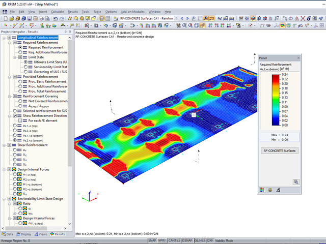
Moduł RF-CONCRETE Surfaces umożliwia wymiarowanie powierzchni z betonu zbrojonego (ściany, stropy, płyty fundamentowe) zgodnie z ACI 318-19 lub CSA A23.3-19. Powszechnym podejściem przy wymiarowaniu płyt jest zastosowanie pasm obliczeniowych do określenia średnich sił wewnętrznych w danym kierunku na szerokości pasma. Metoda ta sprowadza się zasadniczo do analizy elementu dwukierunkowo zbrojonego jako wydzielonych elementów jednokierunkowo zbrojonych, aby określić wymagane zbrojenie wzdłuż danego pasma.