


The serviceability configuration is divided into several tabs, which clearly structure the specifications for the individual design checks.
Members
In the “Members” tab of the “Serviceability Configuration” dialog box, you can define the limit values that apply to the deformations of members and member sets.

Serviceability Limits (Deflections)
For the serviceability limit state design, you can define specific limit values for the deflections, each related to the directions of the member axes.
The deformation limit values are generally related to the lengths of the structural components: The longer a member, the greater the allowable deflection. In the list next to the “Definition type” option, you can select the way in which you would like to define the limit value.
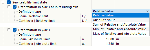
- Relative Value: The limit value is defined in relation to the length of the member or member set.
- Absolute Value: The value of the maximum deflection is specified directly.
- Sum of Relative and Absolute Values: The limit value is calculated by adding the relative value and the absolute value.
- Min. of Relative and Absolute Value: The smaller value of the relative or absolute value is used as the limit value.
- Max. of Relative and Absolute Value: The greater value of the relative or absolute value is used as the limit value.
Depending on how the structural component is supported—a “beam” supported on both sides or a “cantilever” supported on one side—different deflection limits are generally relevant. The type that applies to a specific segment is automatically determined based on the assigned design supports: A segment with design supports on both sides or without design supports is classified as a beam, while a segment with a design support on one side is classified as a cantilever. You can define the design supports in the Design Supports and Deflection tab of the members and member sets.
If necessary, adjust the preset limit values for the deformation analyses of the objects.
If a precamber (pre-deformation of the structural component during assembly) is to be taken into account in the deformation analysis, you can specify this precamber in the properties of the member or member set (see the chapter Design Supports and Deflection). There, you can also specify whether the maximum displacements refer to the shifted segment ends or the undeformed initial system.
Surfaces
In the “Surfaces” tab of the “Serviceability Configuration” dialog box, you can define the limit values that apply to the deformations of the surfaces.

The deflection limits are related to the lengths of the structural components. The list next to the “Definition type” contains several options for defining a limit value (see the image Defining Deformation Reference):
- Relative Value: The limit value is related to the length of the surface.
- Absolute Value: The maximum deflection value is defined directly.
- Sum of Relative and Absolute Values: The limit value is the sum of the relative value and the absolute value.
- Min. of Relative and Absolute Values: The limit value is the smaller of the relative and absolute values.
- Max. of Relative and Absolute Values: The limit value is the greater of the relative and absolute values.
Depending on how the structural component is supported—support on both sides or one-sided support—different deflection limits are usually relevant. This support is defined as the “surface type” in the properties of the surface or surface set in the Deflection tab. There, you can also specify whether the maximum displacements refer to the undeformed structural system, a deformed reference plane, or a parallel surface, and specify how the reference length should be determined.
If necessary, adjust the preset limit values for the deformation analyses of the objects.