176 Results
View Results:
Sort by:

Using the Timber Design add-on, timber column design is possible according to the 2018 NDS standard ASD method. Accurately calculating timber member compressive capacity and adjustment factors is important for safety considerations and design. The following article will verify the maximum critical buckling strength calculated by the Timber Design add-on using step-by-step analytical equations as per the NDS 2018 standard including the compressive adjustment factors, adjusted compressive design value, and final design ratio.
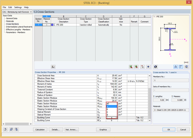
You can adjust the buckling curve of a cross-section in RF-/STEEL EC3, if necessary. This can be done in Window 1.3, Cross‑Sections.

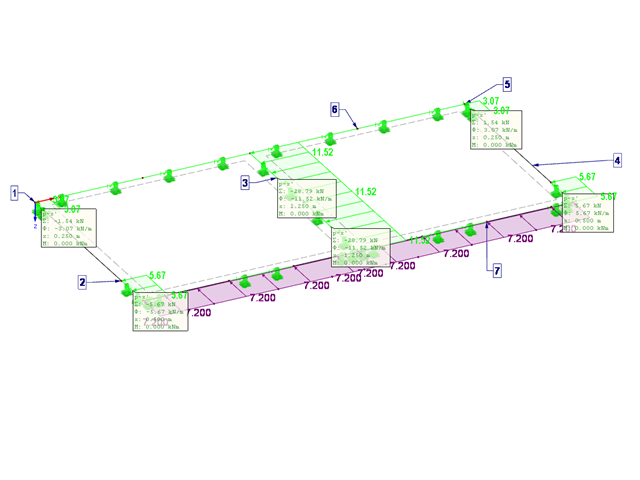
For relatively large or relatively small surfaces, it can happen that the automatically created result values do not fit the model: In the case of large surfaces, there can be too many result values; in the case of small surfaces, too few.

The design of an Ordinary Concentrically Braced Frame (OCBF) and a Special Concentrically Braced Frame (SCBF) can be carried out in the Steel Design add-on of RFEM 6. The seismic design result according to AISC 341-16 and 341-22 is categorized into two sections: Member Requirements and Connection Requirements.

The Steel Design add-on in RFEM 6 now offers the ability to perform seismic design according to AISC 341-16 and AISC 341-22. Five types of seismic force-resisting systems (SFRS) are currently available.

Moment frame design according to AISC 341-16 is now possible in the Steel Design add-on of RFEM 6. The seismic design result is categorized into two sections: member requirements and connection requirements. This article covers the required strength of the connection. An example comparison of the results between RFEM and the AISC Seismic Design Manual [2] is presented.

The three types of moment frames (Ordinary, Intermediate, Special) are available in the Steel Design add-on of RFEM 6. The seismic design result according to AISC 341-16 is categorized into two sections: member requirements and connection requirements.

The three types of moment frames (Ordinary, Intermediate, Special) are available in the Steel Design add-on of RFEM 6. The seismic design result according to AISC 341-22 is categorized into two sections: member requirements and connection requirements.

Utilizing the RF-STEEL AISC add-on module, steel member design is possible according to the AISC 360-16 standard. The following article will compare the results between calculating lateral torsional buckling according to Chapter F and Eigenvalue Analysis.

The design of cold-formed steel members according to the AISI S100-16 is now available in RFEM 6. Design can be accessed by selecting “AISC 360” as the standard in the Steel Design add-on. “AISI S100” is then automatically selected for the cold-formed design (Image 01).

Custom sections are often required in cold-formed steel design. In RFEM 6, the custom section can be created using one of the “Thin-Walled” sections available in the library. For other sections that do not meet any of the 14 available cold-formed shapes, the sections can be created and imported from the standalone program, RSECTION. For general information on AISI steel design in RFEM 6, refer to the Knowledge Base article provided at the end of the page.

Besides the standardized gamma method, you can display the semi-rigid composite beams also as a framework model.

When designing bending-resistant connections from I-beams, the connection is dissolved into the individual parts. For these basic components of a joint, there are separate formula calculators for load-bearing capacity and stiffness. In RFEM and RSTAB, frame joints can be designed using the RF-/FRAME-JOINT Pro add-on module.

The ASCE 7-22 Standard [1], Sect. 12.9.1.6 specifies when P-delta effects should be considered when running a modal response spectrum analysis for seismic design. In the NBC 2020 [2], Sent. 4.1.8.3.8.c gives only a short requirement that sway effects due to the interaction of gravity loads with the deformed structure should be considered. Therefore, there may be situations where second-order effects, also known as P-delta, must be considered when carrying out a seismic analysis.

In RF‑/STEEL EC3, you can assign the same input data to several members or sets of members at the same time. The simultaneous assignment of the input data is possible for intermediate supports, effective lengths, nodal supports, member end hinges, and shear panel and rotational restraint.

The classification of cross-sections according to EN 1993‑1‑1 and EN 1993‑1‑5 can be carried out automatically in the RF‑/STEEL EC3 add-on module. The maximum c/t ratios are specified in the standard for straight cross-section parts. There are no normative specifications for curved cross-section parts; therefore, the cross-section classification cannot be performed for these cross-section parts.
.png?mw=640&hash=6e011ea537587ceb48d9e642d642150a151c551e)
The ASCE 7-16 standard requires both balanced and unbalanced snow load case scenarios for a structure's design consideration. While this may be more intuitive for flat or even gable/hip type roofs, the determination of snow loads is increasingly difficult for arch roofs due to complex geometry. However, with guidance from ASCE 7-16 on snow load calculations for curved roofs and RFEM's efficient load application tools, it is possible to consider both balanced and unbalanced snow loads for a reliable and safe structure design.

In January 2015, DIN Committee NA 005‑08‑23 Steel Bridges applied the introduction of a modification in equation 10.5 of DIN EN 1993‑1‑5. This involves the interaction of longitudinal and transverse pressure in a buckling analysis. Now, the interaction equation provides for auxiliary factor V, which is calculated from the reduction factors of the longitudinal and transverse stresses.

The buckling analysis of plates with stiffeners is a special task for engineers. For this, EN 1993-1-5 provides three calculation methods: Effective Cross-Section Method, [1], Sect. 4-7; Reduced Stress Method, [1], Sect. 10; Finite Element Methods of Analysis (FEM), [1], Annex C.

The stiffening of timber structures is usually carried out by means of timber panels. For this purpose, structural components consisting of slabs (chipboard, OSB) are connected with members. Several articles will describe the basics of this construction method and the calculation in the RFEM program. This first article describes the basic determination of the stiffnesses as well as the calculation.

The calculation of timber panels is carried out on simplified member or surface structures. This article describes how to determine the required stiffness.
This article describes the design of timber panel walls due to generated horizontal loads.

In this example, the design resistance of an end plate according to EN 1993-1-8 [1] is to be determined; the other components are not described here. To check the results, the dimensions of the connection IH 3.1 B 30 24 of Typified Connections [2] were used. S 235 material and bolts with strength 10.9 are used.

Prior to the analysis of steel cross‑sections, the cross‑sections are classified according to EN 1993‑1‑1, Sec. 5.5, with respect to their resistance and rotation capacity. Thus, the individual cross-section parts are analyzed and assigned to Classes 1 to 4. The cross-section classes are determined subsequently and usually assigned to the highest class of the cross-section parts. If plastic resistance is to be applied to further design of cross-sections of Class 1 and Class 2, you can analyze the elastic resistance of cross-sections as of Class 3. In the case of cross-sections of Class 4, local buckling occurs even before reaching the elastic moment. In order to take this effect into account, you can use effective widths. This article describes the calculation of the effective cross-section properties in more detail.
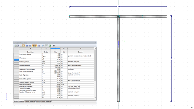
The design of cross-sections usually requires many different cross-section properties. In RFEM and RSTAB, all required properties of standardized cross-sections are available in the cross-section library and can be used directly for the calculation. If the cross-sections are not standardized, SHAPE-THIN allows you to use these cross-sections, too. You can simply enter the geometry to determine all required cross-section properties. The following example shows the calculation of a shear area on a practical example.

In the case of open cross-sections, the torsional load is removed mainly via secondary torsion, since the St. Venant torsional stiffness is low compared to the warping stiffness. Therefore, warping stiffeners in the cross-section are particularly interesting for the lateral-torsional buckling analysis, as they can significantly reduce the rotation. For this, end plates or welded stiffeners and sections are suitable.

Table 3.1 of EN 1993‑1‑8:2010‑12 defines the nominal values of the yield strength and the ultimate limit strength of bolts. The bolt classes given here are 4.6, 4.8, 5.6, 5.8, 6.8, 8.8, 10.9. The note for this table states that the National Annex may exclude certain bolt classes. For the NA of Germany, these are the bolt classes 4.8, 5.8, and 6.8.

When designing a steel cross-section according to Eurocode 3, it is important to assign the cross-section to one of the four cross-section classes. Classes 1 and 2 allow for a plastic design; classes 3 and 4 are only for elastic design. In addition to the resistance of the cross-section, the structural component's sufficient stability has to be analyzed.
![System and Loading According to [1]](/en/webimage/009455/2418877/01-en-png.png?mw=640&hash=c76563b459152b19c98197ea6ba342be89d9a5bc)
The product range of Dlubal Software contains various modules for the design of steel and timber connections. The RF-/JOINTS Steel – Column Base add-on module allows you to analyze footings of hinged or restrained steel column bases. The fastener selection, foundation geometry, and material quality are crucial for the cost-effective and safe design of the column base.

The automatic creation of combinations in RFEM and RSTAB with the "EN 1990 + EN 1991‑3; Cranes" option allows you to design crane runway beams as well as support loads on the rest of the structure.