31 Wyniki
Wyświetl wyniki:
Sortuj według:

Analiza wyboczenia giętnego jest połączeniem analizy stateczności i stanu granicznego nośności, stosowana w konstrukcjach stalowych od setek lat. Punktem wyjścia do rozważenia kwestii stateczności jest krytyczne obciążenie wyboczeniowe, ale dotychczas nie przeprowadzono obliczeń bez uwzględnienia imperfekcji. Jak dokładnie określane są te imperfekcje?

Aby ocenić, czy w obliczeniach dynamicznych konieczne jest również uwzględnienie analizy drugiego rzędu, w normie EN 1998‑1, sekcje 2.2.2 i 4.4.2.2 zawarto współczynnik wrażliwości międzykondygnacyjnego znoszenia θ. Można ją obliczyć i przeanalizować za pomocą programów RFEM 6 i RSTAB 9.
Zgodnie z normami EN 1998-1 sekcje 2.2.2 i 4.4.2.2 do obliczeń stanu granicznego nośności należy przeprowadzić obliczenia z uwzględnieniem teorii drugiego rzędu (efekt P-Δ). Efekt ten nie musi być uwzględniany tylko w przypadku, gdy współczynnik wrażliwości międzykondygnacyjnej jest mniejszy niż 0,1.

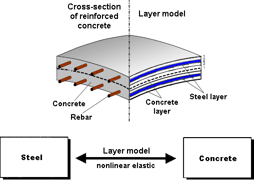
W tym artykule opisano na przykładzie płyty z betonu włóknistego, które wpływają na zastosowanie różnych metod całkowania i różnej liczby punktów całkowania na wynik obliczeń.
Wraz z programami do analizy statyczno-wytrzymałościowej RFEM 6, RSTAB 9, RSECTION 1 i RWIND 2, Dlubal Software przedstawia nową generację programów do analizy statyczno-wytrzymałościowej. Getreu dem Motto „Statik, die Spaß macht…“ werden den Anwendern universelle Werkzeuge in die Hand gegeben, mit denen alle Anforderungen in der Tragwerksplanung bewältigt werden können. Was sich sonst noch bei Dlubal Software Neues getan hat, erfahren Sie in diesem Artikel.
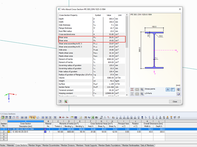
Właściwości przekrojów w RFEM i RSTAB uwzględniają różne typy powierzchni ścinania. W tym artykule technicznym wyjaśniono sposób obliczania i znaczenie różnych wartości.
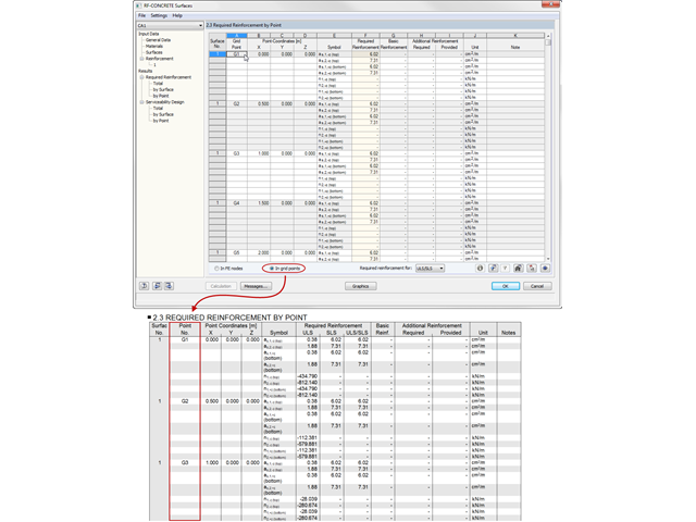
Die Ergebnisse aus RF-BETON Flächen können im Ausdruckprotokoll tabellarisch dokumentiert werden.
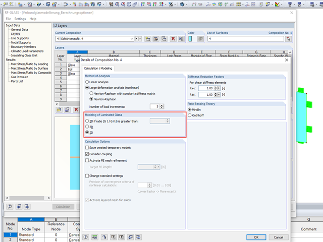
Bei der Glasbemessung im Zusatzmodul RF-GLAS stehen grundsätzlich zwei verschiedene Berechnungsoptionen zur Verfügung: eine 2D- und eine 3D-Berechnung. Grundsätzlicher Unterschied dieser beiden Bemessungsvarianten ist die vom Programm automatisierte Modellierung der Scheiben im temporären Modell. Bei einer 2D-Bemessung werden für die einzelnen Scheiben gängige Flächenelemente (Plattentheorie) generiert, während bei der 3D-Bemessung die einzelnen Scheiben als Volumen abgebildet werden. Je nach gewähltem Schichtaufbau steht die Option zur Wahl oder wird vom Programm bereits automatisch vorgegeben.
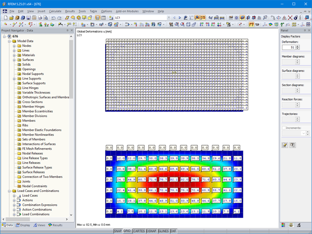
W przypadku stosunkowo dużych i stosunkowo małych powierzchni, może się zdarzyć, że automatycznie utworzone wartości wyników nie będą pasowały do modelu: Die Ergebnisse werden bei großen Flächen entweder zu häufig erzeugt oder bei kleinen Flächen zu wenig.
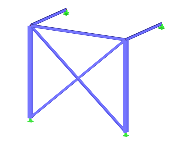
Wenn die Berechnung eines Stabmodells nach Theorie II. Ordnung mit einer Fehlermeldung endet, liegt die Ursache dieser Instabilität nicht selten an ausgefallenen Zugstäben: Sobald in einem Berechnungsschritt Druckkräfte in einem Zugstab auftreten, wird dieser Stab in den folgenden Iterationen nicht mehr berücksichtigt. Dadurch kann das Modell instabil werden.
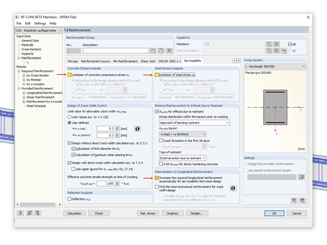
In RF-BETON Stäbe und BETON steht die Option zur "Auslegung der Längsbewehrung für den Grenzzustand der Gebrauchstauglichkeit" zur Verfügung. Dabei können die Auslegungskriterien für die Berechnung der Längsbewehrung ausgewählt werden.
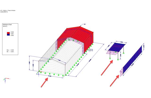
Wiatr wiejący równolegle do powierzchni konstrukcji może generować siły tarcia na tych powierzchniach. Dieser Effekt ist vor allem meist bei sehr großen Bauwerken von Interesse.
Menadżer projektów jest instalowany domyślnie podczas instalacji programów RFEM oraz RSTAB i ułatwia zarządzanie wszystkimi projektami oraz plikami obliczeniowymi. W Menadżerze projektów można połączyć kilka różnych projektów, dzięki czemu użytkownik ma wygodny i przejrzysty podgląd plików programu. Obie metody mają różne cechy i mogą być mniej lub bardziej odpowiednie w zależności od okoliczności. W tym artykule przedstawiono przegląd dwóch metod obliczeniowych.
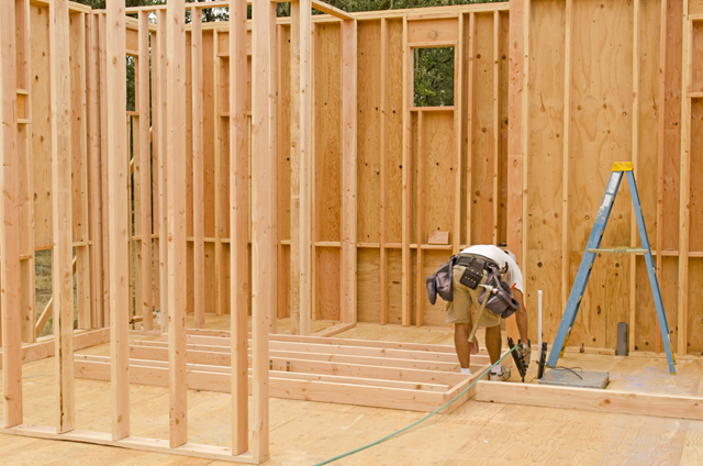
Usztywnienie konstrukcji drewnianych jest zwykle realizowane za pomocą drewnianych paneli. Hierfür werden plattenartige Werkstoffe (Grobspanplatten, OSB) mit Stäben verbunden. In mehreren Beiträgen werden die Grundlagen dieser Bauweise und die Berechnung im Programm RFEM erläutert. In diesem ersten Beitrag wird die grundlegende Ermittlung der Steifigkeiten sowie die Berechnung erläutert.
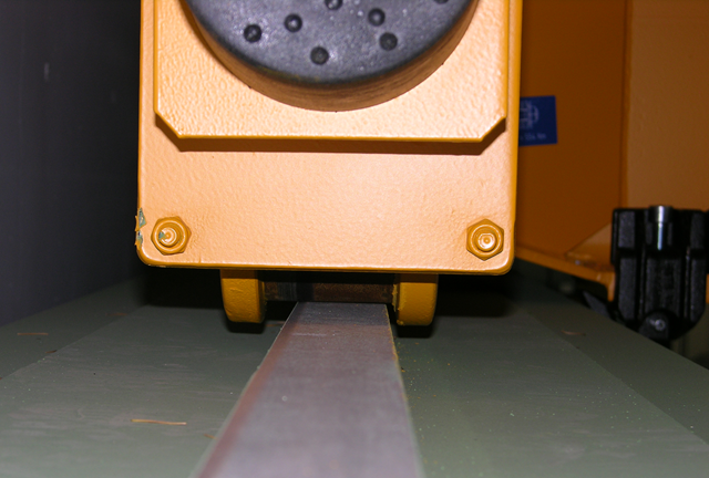
Bei Kranbahnen mit großen Stützweiten ist nicht selten die Horizontallast aus Schräglauf bemessungsrelevant. In diesem Beitrag sollen die Entstehung dieser Kräfte und die richtige Eingabe in KRANBAHN beschrieben werden. Es wird hierbei auf die praktische Ausführung und den theoretischen Hintergrund eingegangen.
Die Berechnung in RFEM erfolgt meist in mehreren Rechenschritten, den sogenannten Iterationen. Damit können zum einen besondere Modelleigenschaften berücksichtigt werden wie beispielsweise Objekte mit nichtlinearen Funktionen. Zum anderen werden durch eine iterative Berechnung nichtlineare Effekte erfasst, die sich durch Verformungs- und Schnittgrößenänderungen bei Theorie II. Ordnung oder unter Berücksichtigung großer Verformungen (Seiltheorie) ergeben. Bei komplexen Modellen sind geometrisch lineare Berechnungen in der Regel nicht ausreichend.
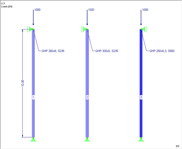
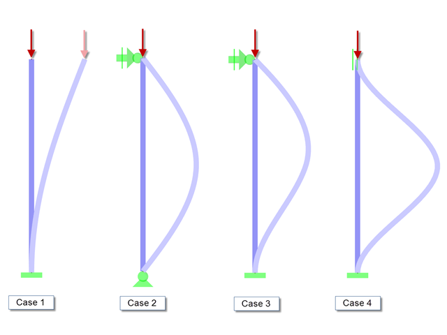
Niniejszy artykuł dotyczy analizy stateczności słupa stalowego poddanego ściskaniu osiowemu zgodnie z EN 1993-1-1, rozdz. 6.3.1. Zusätzlich wird eine Variantenuntersuchung mit dem Ziel der Stahloptimierung durchgeführt.
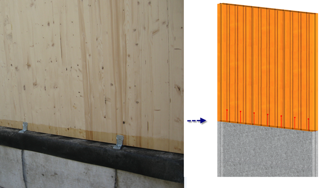
W tym artykule omówiono uwzględnienie zwolnień na końcach powierzchni między powierzchniami za pomocą przegubów liniowych i zwolnień liniowych. Mit Liniengelenken und Linienfreigaben werden Nachgiebigkeiten zwischen Flächen berücksichtigt. Beispiele hierfür sind Trennfugen im Stahlbetonbau oder Eckverbindungen im Brettsperrholzbau.
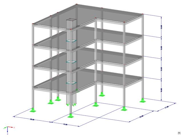
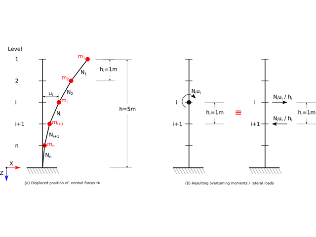
Die Geschossverschiebung eines Gebäudes liefert wertvolle Informationen über sein Tragverhalten unter seismischen Beanspruchungen. Diese können zu großen horizontalen Verformungen und sogar zu Instabilitäten führen. Einige Normen fordern deshalb die Kontrolle der Geschossverschiebung in seinem Massenschwerpunkt. Daraus kann man zum Beispiel ablesen, ob eine Berechnung nach Theorie II. Ordnung (P-Δ-Effekt) durchgeführt werden soll.
![Spektrale Beschleunigung Sa [m/s²] versus Eigenfrequenz f [Hz] eines schmalbandigen Antwortspektrums nach EN 1998-1 [1]](/pl/webimage/009251/466397/01-de.png?mw=640&hash=9f6ca6566391e0348354d64018782d9ffd5f7c70)
In einem multimodalen Antwortspektrenverfahren ist es wichtig, eine ausreichende Anzahl von Eigenwerten der Struktur zu ermitteln und deren dynamische Antworten zu berücksichtigen. Vorschriften wie die EN 1998-1 [1] und andere internationale Standards schreiben vor, 90 % der Strukturmasse zu aktivieren. To oznacza: so viele Eigenwerte zu bestimmen, dass die Summe der effektiven Modalmassenfaktoren größer 0.9 ist.
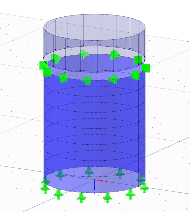
Das Schalenbeulen gilt als das jüngste und am wenigsten erforschte Stabilitätsproblem der Bautechnik. Dies liegt weniger an mangelnden Forschungsaufwendungen, sondern vielmehr an der Komplexität der Theorie. Mit der Einführung und Fortentwicklung der Finite-Elemente-Methode in der bautechnischen Praxis erscheint es manchem Ingenieur nicht mehr erforderlich, sich mit der komplizierten Theorie des Schalenbeulens auseinanderzusetzen. Zu welchen Problemen und Fehlern dies führen kann, ist in [1] sehr gut zusammengefasst.
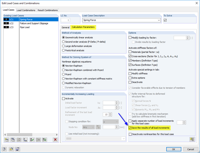
Zgodnie z normą EN 1993‑1‑1 [1] konieczne jest zastosowanie zastępczych imperfekcji geometrycznych o wartościach odzwierciedlających możliwe efekty wszystkich typów imperfekcji. In EN 1993‑1‑1 Abschnitt 5.3 werden die grundsätzlichen Imperfektionen für die Tragwerksberechnung sowie die Bauteilimperfektionen angegeben.
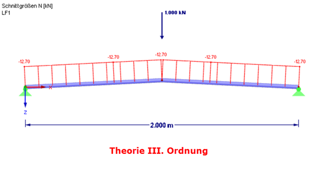
W przypadku uszkodzenia postkrytycznego następuje istotna zmiana geometrii konstrukcji. Nach dem Erreichen der Instabilität des Gleichgewichts wird wieder eine stabile, tragfähige Lage erreicht. Analiza postkrytyczna wymaga podejścia "eksperymentalnego". Obciążenie w takim przypadku należy zwiększać stopniowo.
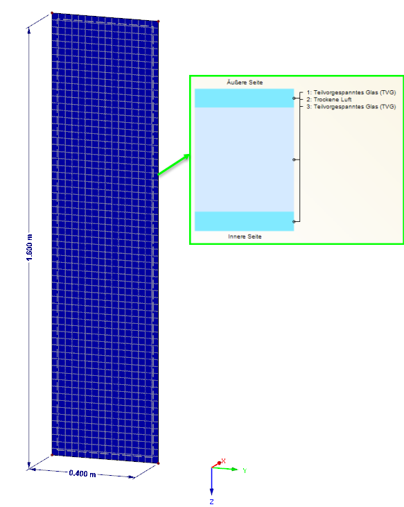
Obciążenie tafli szkła izolacyjnego spowodowane wpływami klimatycznymi jest wyraźnie uregulowane w normie DIN 18008. Diese Art der Belastung kann bei entsprechender Scheibengeometrie auch maßgebend für die Bemessung im Zustand der Tragfähigkeit werden. Eine FE-Bemessung am Gesamtsystem mit Abbildung des SZR als Gasvolumen liefert exakte Ergebnisse zur Analyse. Im Gegenzug gewinnt jedoch auch eine stichpunktartige Plausibilitätskontrolle immer mehr an Bedeutung. Nachfolgend werden verschiedene Optionen aufgezeigt, wie diese Kontrollen durchgeführt werden können.
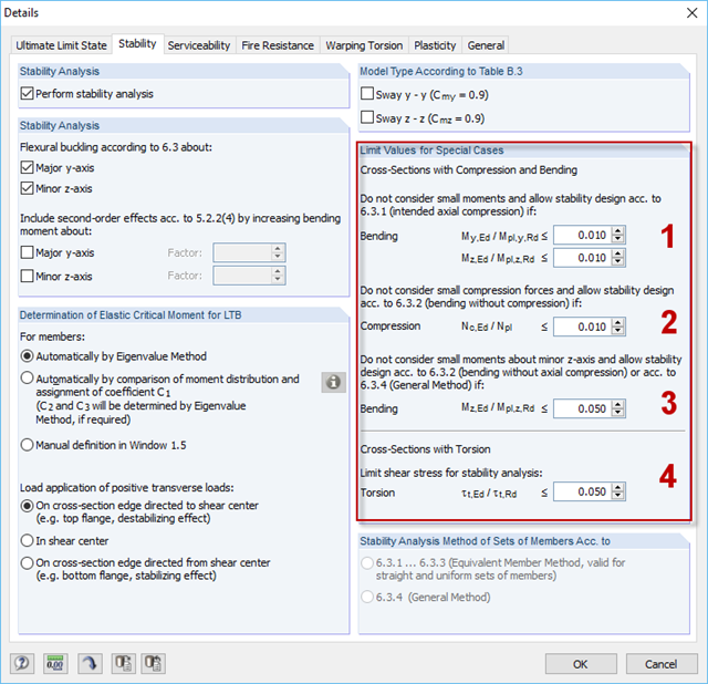
W sytuacjach, w których nie są dostępne obliczenia, w module RF-/STEEL EC3 można pominąć odpowiednie siły wewnętrzne. Przykładami takich sytuacji są: zginanie i ściskanie na kątownikach, zginanie wieloosiowe do obliczeń według metody ogólnej, skręcanie.
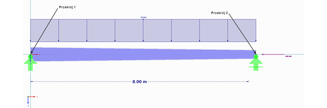
W artykule przedstawiono analizę metodą numeryczną belki zginanej z otworem kołowym. Dabei wird als Anhaltspunkt das Beispiel eines Lochträgers aus [1] verwendet. Die dortige Modellierung als 3D-Modell wurde hier vereinfacht auf eine zweidimensionale Diskretisierung heruntergebrochen.
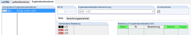
Programy RFEM i RSTAB oferują dwie różne metody superpozycji przypadków obciążeń. Mit Lastkombinationen werden die Lasten der einzelnen Lastfälle überlagert und in einem "großen Lastfall" zusammen berechnet. Ergebniskombinationen kombinieren hingegen nur die Ergebnisse der einzelnen Lastfälle. Der Beitrag wird sich nun im Folgenden mit den Grundlagen der Definition von Ergebniskombinationen befassen und diese an zwei Beispielen näher erläutern.
![Redukcja budynku do konstrukcji wspornikowej. Kondygnacje stanowią poszczególne punkty masy. Ugięcie spowodowane normalnymi siłami ściskającymi pokazanymi w (a) jest (b) przeliczane na równoważne momenty przemieszczenia lub siły tnące [2]]](/pl/webimage/009762/467694/01-de-png.png?mw=640&hash=52805a227240ecddbd69b1d113348bf2749c3f9e)
Zgodnie z EN 1998-1 sekcje 2.2.2 i 4.4.2.2 [1] do sprawdzania stanu granicznego nośności należy przeprowadzić obliczenia z uwzględnieniem teorii drugiego rzędu (efekt P-Δ). Dieser Einfluss darf nur vernachlässigt werden, wenn der Empfindlichkeitsbeiwert der gegenseitigen Stockwerksverschiebung θ kleiner 0,1 ist.
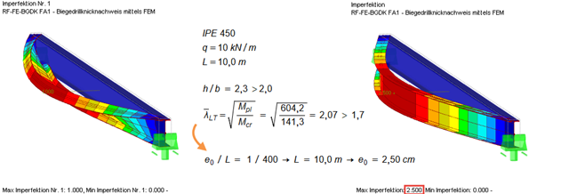
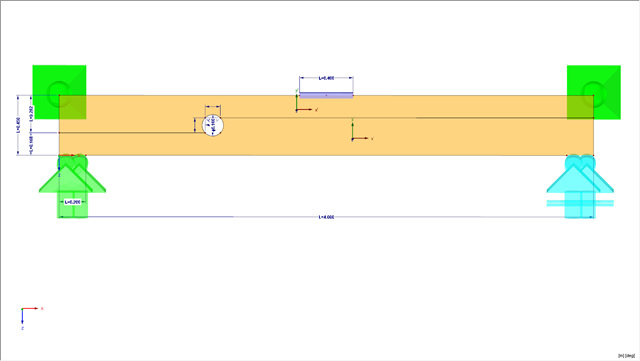
Poniższy artykuł opisuje wymiarowanie belki jednoprzęsłowej poddanej zginaniu i ściskaniu, które jest przeprowadzane zgodnie z EN 1993-1-1 w module dodatkowym RF-/STEEL EC3. Da der Träger als gevouteter Querschnitt ausgeführt ist und es sich damit nicht um ein gleichförmiges Bauteil handelt, ist der Nachweis entweder nach dem Allgemeinen Verfahren nach Abs. 6.3.4 EN 1993-1-1 zu führen oder mittels Theorie II. Ordnung. Beide Möglichkeiten sollen untersucht und verglichen werden, wobei für die Berechnung nach Theorie II. Ordnung ein zusätzliches Nachweisformat mittels Teilschnittgrößenverfahren zur Verfügung steht. Daraus gliedert sich die Bemessung in drei Schritte:Nachweis nach Abs. 6.3.4 EN 1993-1-1 (Allgemeines Verfahren)Nachweis nach Theorie II. Ordnung, elastisch (Wölbkrafttorsionsanalyse)Nachweis nach Theorie II. Ordnung, plastisch (Wölbkrafttorsionsanalyse und Teilschnittgrößenverfahren)
Soll der Stabilitätsnachweis von Stäben nach dem Ersatzstabverfahren unter Berücksichtigung der Schnittgrößen nach Theorie I. Ordnung geführt werden, ist die Bestimmung der maßgebenden Ersatzstablänge von großer Bedeutung.