53 Results
View Results:
Sort by:

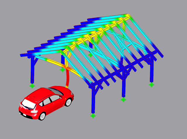
If a canopy roof (for example, a filling station roof) should be designed, a load determination with regard to Section 7.3 of EN 1991-1-4 is required. This article shows the design of a slightly inclined troughed roof, with an example.

In Germany, DIN EN 1991-1-4 with the National Annex DIN EN 1991-1-4/NA regulates the wind loads. The standard applies to civil engineering works up to an altitude of 300 m.

Wind is the only climatic load acting on every type of structure in every country in the world, unlike snow. The wind speed depends on the geographic location of the building. Currently, this is one of the main reasons for the necessity of regional division (wind zone) and consideration of the altitude stipulated within the official standards; the variation of the dynamic pressures according to the height above the ground for a "normal" site deprived of masking effect should be taken into account as well.

- 001530
- Modeling | Loading
- RFEM 5
-
- RSTAB 8
- RX-TIMBER Glued-Laminated Beam 2
- RX-TIMBER Roof 2
- RX-TIMBER Continuous Beam 2
- RX-TIMBER Purlin 2
- RX-TIMBER Frame 2
- RX-TIMBER Column 2
- RX-TIMBER Brace 2
- Buildings
- Concrete Structures
- Steel Structures
- Timber Structures
- Process Manufacturing Plants
- Temporary Structures
- Structural Analysis & Design
- Eurocode 1
- Eurocode 0
In Germany, DIN EN 1991-1-3 with National Annex DIN EN 1991-1-3/NA regulates snow loads. The standard applies to civil engineering works at altitudes of up to 1,500 m above sea level.
The fundamental requirements of a structural system are (according to the basis of structural design) sufficient ultimate limit state, serviceability, and resistance. Structures must be designed in such a way that no damage occurs due to events such as the impact of a vehicle.
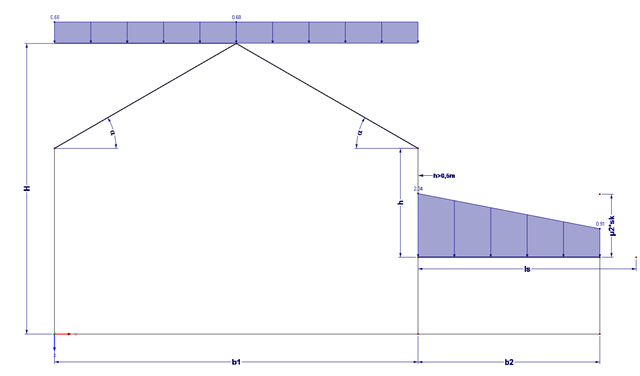
Buildings often have extensions. If the roof levels are not at the same height, this height difference (if more than 0.5 m) must additionally be considered for the snow load assumption.

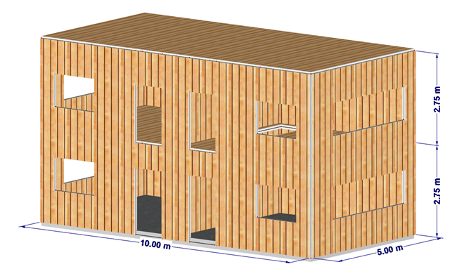
The stiffening of timber structures is usually carried out by means of timber panels. For this purpose, structural components consisting of slabs (chipboard, OSB) are connected with members. Several articles will describe the basics of this construction method and the calculation in the RFEM program. This first article describes the basic determination of the stiffnesses as well as the calculation.
This article describes the determination of force coefficients using a wind load and the calculation of a stability factor due to lateral-torsional buckling.

For crane runways with large spans, the horizontal load from skewing is often relevant for the design. This article describes the origin of these forces and the correct input in CRANEWAY. The practical implementation and the theoretical background are discussed.

Slender bending beams that have a large h/w ratio and are loaded parallel to the minor axis tend to have stability issues. This is due to the deflection of the compression chord.
![Forked Beam with Distributed Load (Source: [3])](/en/webimage/009690/467522/01-de-png.png?mw=640&hash=52805a227240ecddbd69b1d113348bf2749c3f9e)
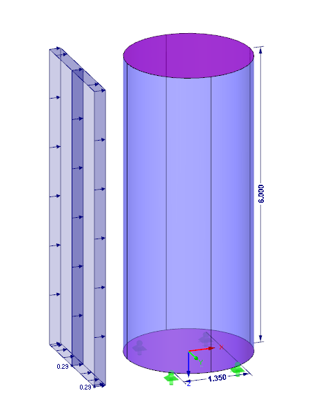
Long-span glued-laminated beams are usually supported by a reinforced concrete column with torsional restraints.
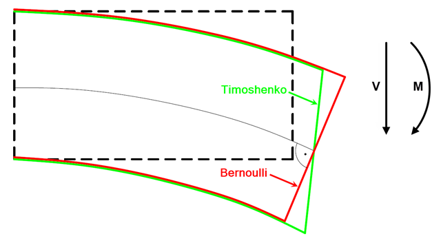
In current literature, the formulas used to determine internal forces and deformations manually are usually specified without considering the shear deformation. The deformations resulting from shear force are often underestimated in timber construction in particular.

In accordance with Sec. 6.6.3.1.1 and Sec. 10.14.1.2 of ACI 318-14 and CSA A23.3-14, respectively, RFEM effectively takes into consideration concrete member and surface stiffness reduction for various element types. Available selection types include cracked and uncracked walls, flat plates and slabs, beams, and columns. The multiplier factors available within the program are taken directly from Table 6.6.3.1.1(a) and Table 10.14.1.2.

In addition to the basic combination rules of EN 1990, there are other combination conditions for actions on road bridges specified in EN 1991‑2 that must be taken into account. RFEM and RSTAB provide automatic combinatorics that can be activated in the General Data when selecting the standard EN 1990 + EN 1991‑2. The partial safety factors and combination coefficients depending on the action category are preset when selecting the respective National Annex.

The calculation of timber panels is carried out on simplified member or surface structures. This article describes how to determine the required stiffness.

Wind blowing parallel to the surfaces of a structure can generate friction forces on these surfaces. This effect is important mainly for very large structures.

In the existing standard, there were no regulations for the distribution of snow loads for elevated solar thermal and photovoltaic systems on roofs. Only distribution of the loads was advised. It was only with the National Annex DIN EN 1991-1-3/NA: 2019-04 that specific regulations were made for this.

- 001555
- Modeling | Loading
- RFEM 5
-
- RSTAB 8
- RF-TIMBER AWC 5
- TIMBER AWC 8
- RF-TIMBER CSA 5
- TIMBER CSA 8
- RF-TIMBER Pro 5
- TIMBER Pro 8
- RF-JOINTS Timber | Timber to Timber 5
- JOINTS Timber | Timber to Timber 8
- RF-JOINTS Timber | Steel to Timber 5
- JOINTS Timber | Steel to Timber 8
- RF-LIMITS 5
- LIMITS 8
- RF-LAMINATE 5
- Timber Structures
- Laminate and Sandwich Structures
- Structural Analysis & Design
- Finite Element Analysis
- Steel Connections
- Eurocode 0
- Eurocode 5
- ANSI/AISC 360
- SIA 260
- SIA 265
In addition to determining loads, some particularities concerning the load combinatorics in timber design have to be considered. Contrary to steel structures, where the largest loading results from all unfavorable actions, in timber construction, the strength values depend on the load duration and timber humidity. Special characteristics have to be considered as well for the serviceability limit state design. The following article discusses the effects on the design of wooden elements and how this is possible with RSTAB and RFEM.
The wind loads are regulated according to Eurocode 1 - Actions on Structures - Part 1-4: General actions - Wind loads. The nationally determined parameters of a respective country can be found in the National Annexes.

The article titled Lateral-Torsional Buckling in Timber Construction | Theory explains the theoretical background for the analytical determination of the critical bending moment Mcrit or the critical bending stress σcrit for the lateral buckling of a bending beam. This article uses examples to verify the analytical solution with the result from the eigenvalue analysis.

In RFEM 5 and RSTAB 8, you can design foundations according to EN 1992‑1‑1 and EN 1997‑1 in the RF‑/FOUNDATION Pro add‑on module.

Using the RF-TIMBER CSA module, timber column design is possible according to the CSA O86-19 standard. Accurately calculating timber member compressive resistance and adjustment factors is important for safety considerations and design. The following article will verify the factored compressive resistance in the RFEM add-on module RF-TIMBER CSA, using step-by-step analytical equations as per the CSA O86-19 standard including the column modification factors, factored compressive resistance, and final design ratio.

With RF-/STEEL EC3, you can utilize nominal temperature-time curves in RFEM and RSTAB. The standard time-temperature curve (ETK), the external fire curve and the hydrocarbon fire curve are implemented. Moreover, the program provides the option to directly specify the final temperature of steel.
![Structural System and Cross-Section Dimensions According to [1]](/en/webimage/009153/2417271/01-en-png.png?mw=640&hash=c76563b459152b19c98197ea6ba342be89d9a5bc)
There are several options for calculating a semi-rigid composite beam. They differ primarily in the type of modeling. Whereas the Gamma method ensures simple modeling, additional efforts are required when using other methods (for example, shear analogy) for the modeling which are, however, offset by the much more flexible application compared to the Gamma method.
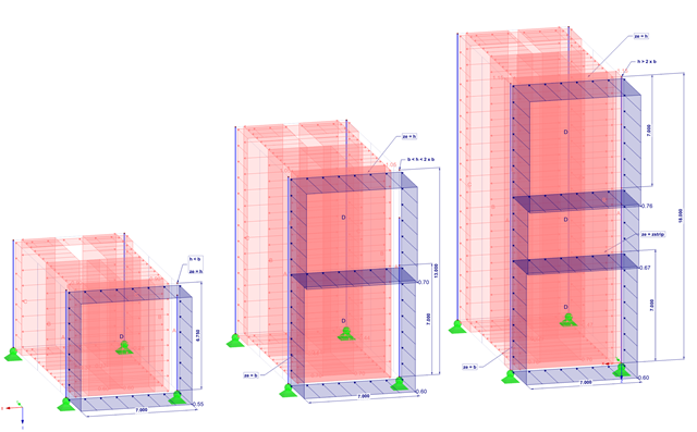
This article shows the effect of the different stiffnesses of the timber panel walls on the floor plan.
This article describes the design of timber panel walls due to generated horizontal loads.

The Eurocode for DIN EN 1991‑1‑4:2010‑12 describes wind loads acting on structural systems.

This article describes how a flat slab of a residential building is modeled in RFEM 6 and designed according to Eurocode 2. The plate is 24 cm thick and is supported by 45/45/300 cm columns at distances of 6.75 m in both the X and Y directions (Image 1). The columns are modeled as elastic nodal supports by determining the spring stiffness based on the boundary conditions (Image 2). C35/45 concrete and B 500 S (A) reinforcing steel are selected as the materials for the design.

Besides the standardized gamma method, you can display the semi-rigid composite beams also as a framework model.

Basically, you can design the structural components made of cross-laminated timber in the RF-LAMINATE add-on module. Since the design is a pure elastic stress analysis, it is necessary to additionally consider the stability issues (flexural buckling and lateral-torsional buckling).