105 Results
View Results:
Sort by:

For structural components consisting of slabs, it is necessary to perform shear design on the locations with concentrated load introduction, applying the punching shear design rules according to Sect. 6.4 of EN 1992‑1‑1 [1]. The concentrated load introduction is present on the individual locations; for example, by columns, concentrated load, or nodal supports. In addition, the end of linear load introduction on slabs is also regarded as concentrated load introduction. For example, this includes wall ends, wall corners, and ends or corners of line loads and line supports. You can perform the punching shear design for floor slabs or foundations, considering the existing available plate topology about the designed node of punching shear. The punching shear design according to EN 1992‑1‑1 checks that the acting shear force vEd does not exceed the resistance vRd.

The secondary reinforcement according to DIN EN 1992-1-1 9.2.1 is used to ensure the desired structural behavior. It should avoid failure without prior notification. The minimum reinforcement has to be arranged independently of the size of the actual loading.
Downstand beams or T-beams are often used in reinforced concrete structures. In contrast to the previous representation and calculation options where, for example, a downstand beam was considered as a fixed support and the determined support reaction was applied to a separate member structure using a T-beam section, the ultimate structural FEA software like RFEM allow you to consider the structure as a whole and thus achieve a more precise analysis.
![Time-Dependent Settlement Components [2]](/en/webimage/009673/2419908/01-en-png-png.png?mw=640&hash=5e657e3feb5c1bb6d21727468dd85d91e1c9f29f)
For the serviceability limit state design according to Section 6.6 of Eurocode EN 1997‑1, settlement has to be calculated for spread foundations. RF-/FOUNDATION Pro allows you to perform the settlement calculation for a single foundation. For this, you can chose between an elastic and a solid foundation. By defining a soil profile, it is possible to consider several soil layers under the foundation base. The results of the settlement, foundation tilting, and vertical soil contact stress distribution are displayed graphically and in tables to provide a quick and clear overview of the calculation performed. In addition to the design of the foundation settlement in RF-/FOUNDATION Pro, the structural analysis determines the representative spring constants for the support and can be exported to the structural model of RFEM or RSTAB.
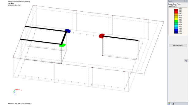
The RF-PUNCH Pro add-on module allows you to perform punching shear design of slabs and foundation plates (floor slabs) on wall ends and wall corners.
![Parameters of Effective Slab Width (Figure 5.3 [1])](/en/webimage/009561/2419376/01-en-png.png?mw=640&hash=c76563b459152b19c98197ea6ba342be89d9a5bc)
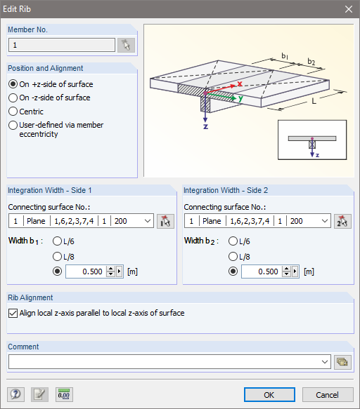
In the case of combined FEM structures (surface and member elements) as well as folded plate structures, it is possible to attribute a beam structure for the design on a member to a fictitious T-beam cross-section, whose geometry depends on the effective width. When using the "Rib" member type in RFEM, the stiffness is represented by a slab component (surface element) and a web component (member element). This approach has some design specifics that are explained in this article.
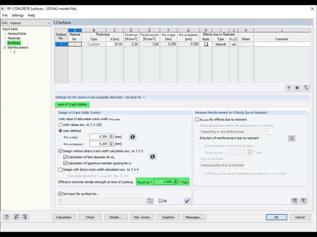
Eurocode 2 provides two ways to perform a crack width design. On one hand, the crack width design according to 7.3.3 can be performed without direct calculation by means of tables for the limitation of the member spacing and diameter. On the other hand, the crack width wk can be determined directly according to 7.3.4 and compared to a limit value.

The classification of cross-sections is intended to determine the limits of resistance and rotational capacity due to local buckling of cross-section parts. In EN 1999‑1‑1, 6.1.4.2 (1), four classes are defined.
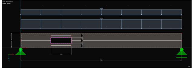
Since the ultimate limit state of beams in the area of openings is affected, particular attention should be paid to this. In general, small openings can be sufficiently covered by adapting the beam structure to the openings. For big openings, it is necessary to consider and model the area separately.
![Structural System for Schöck Isokorb® Type K from [1]](/en/webimage/009555/2419353/01-en-png.png?mw=640&hash=c76563b459152b19c98197ea6ba342be89d9a5bc)
Heat loss due to external components without thermal decoupling of the internal components is enormous. For this reason, external structural components are thermally separated from the building envelope using a special built-in component. For the connection of a balcony slab with a reinforced concrete floor, Schöck Isokorb® or HALFEN HIT Insulated Connection can be used, for example. For the design of such built-in components, the respective technical approval must be taken into account. The following article shows an example of considering Schöck Isokorb® in the FEM calculation.

When defining the effective slab width of T-beams, RFEM provides the predefined widths that are determined as 1/6 and 1/8 of the member length. A more detailed explanation on these two factors is given below.

Determining the Material Properties of Steel-Fiber-Reinforced Concrete and Their Application in RFEM
Steel-fiber-reinforced concrete is mainly used nowadays for industrial floors or hall floors, foundation plates with low loads, basement walls, and basement floors. Since the publication in 2010 of the first guideline about steel-fiber-reinforced concrete by the German Committee for Reinforced Concrete (DAfStb), a structural engineer can use standards for the design of the steel fiber-reinforced concrete composite material, which makes the use of fiber-reinforced concrete increasingly popular in construction. This article explains the individual material parameters of steel-fiber-reinforced concrete and how to deal with these material parameters in the FEM program RFEM.
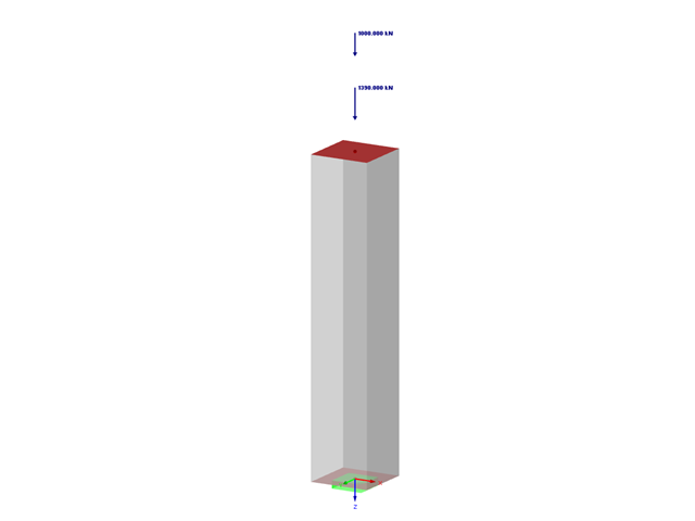
This article deals with rectilinear elements of which the cross-section is subjected to axial compressive force. The purpose of this article is to show how very many parameters defined in the Eurocodes for concrete column calculation are considered in the RFEM 5 structural analysis software.
![Tension Cover Line from [1]](/en/webimage/009390/2418541/01-en-png.png?mw=640&hash=c76563b459152b19c98197ea6ba342be89d9a5bc)
In the case of a large amount of reinforcement, it might be useful to grade the longitudinal reinforcement of a beam, which means: curtailment. The grading corresponds to the tensile force distribution. Using RF-CONCRETE Members and CONCRETE, you can specify the curtailment of the reinforcement, which is considered in the automatically proposed reinforcement for the longitudinal reinforcement. When determining this reinforcement proposal, it is necessary to ensure that the envelope of the acting tensile force can be absorbed.
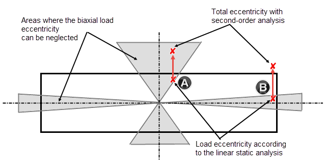
Daily tasks in reinforced concrete design also include designing compression elements subjected to biaxial bending. The following article describes the different methods according to Chapter 5.8.9, EN 1992-1-1, which can be used to design compression elements with biaxial load eccentricities by means of the nominal curvature method according to 5.8.8.

This article deals with elements concerning which the cross-section is subjected simultaneously to a bending moment, a shear force, and an axial compressive or tensile force. However, in our example we will not include loading due to shear force.

In RFEM 5 and RSTAB 8, you can design foundations according to EN 1992‑1‑1 and EN 1997‑1 in the RF‑/FOUNDATION Pro add‑on module.

According to Book 631 of the DAfStb (German Committee for Structural Concrete), Chapter 2.4, the structural behavior of ceilings changes if their continuous support by walls is interrupted in areas of openings. Depending on the length of the opening area and the plate thickness, measures are necessary regarding the analysis of the ceiling in the area of the opening.

Describing the procedure for the serviceability limit state design of a floor slab made of steel fiber reinforced concrete. This article shows how to perform the corresponding design for the SLS by means of the iteratively determined FEA results.
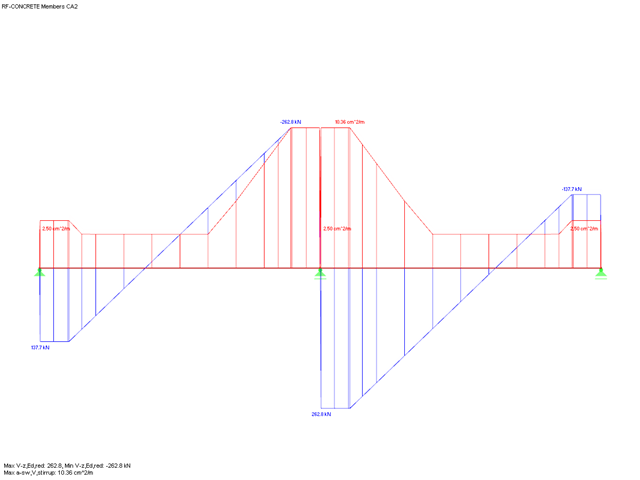
When performing shear force design in RF-CONCRETE Members and CONCRETE, you can reduce the acting shear force Vz according to EN 1992-1-1. The following article describes the reduction of the concentrated loads close to the support and the shear force design at the distance d from the support face for a uniform load.
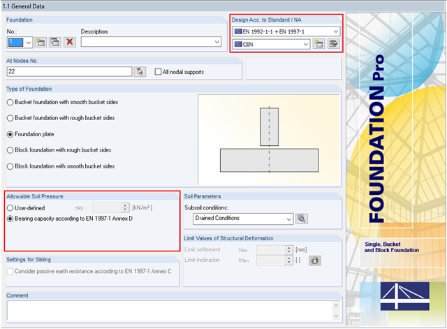
In addition to the reinforced concrete design according to EN 1992‑1‑1, RF-/FOUNDATION Pro allows you to perform geotechnical designs according to EN 1997‑1. In RF-/FOUNDATION Pro, the design of the allowable soil pressure is performed as a ground failure resistance design. If you select CEN as National Annex, you have two options for defining the ground failure resistance. First, you can directly specify the allowable characteristic value of the soil pressure σRk. Second, there is also the option to analytically determine the bearing capacity according to [1], Annex D.

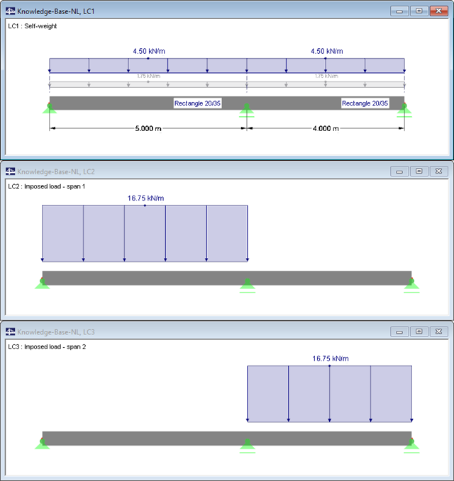
This article describes how a flat slab is generated as a 2D model in RFEM and the loading is applied according to Eurocode 1. The load cases are combined according to Eurocode 0 and calculated linearly. In the RF-CONCRETE Surfaces add-on module, the bending design of the slab is performed while taking into account the standard requirements of Eurocode 2. The reinforcement is complemented by a rebar reinforcement for areas that are not covered by the mesh basic reinforcement.
When designing reinforced concrete components according to EN 1992‑1‑1 [1], nonlinear methods of determining internal forces for the ultimate and serviceability limit states are possible. In this case, the internal forces and deformations are determined with respect to their nonlinear behaviour. The analysis of stresses and strains in cracked state usually provides the deflections, which clearly exceed the linearly determined values.

Steel-fiber-reinforced concrete is mainly used nowadays for industrial floors or hall floors, foundation plates with low loads, basement walls, and basement floors. Since the publication in 2010 of the first guideline about steel-fiber-reinforced concrete by the German Committee for Reinforced Concrete (DAfStb), a structural engineer can use standards for the design of the steel fiber-reinforced concrete composite material, which makes the use of fiber-reinforced concrete increasingly popular in construction. This article describes the nonlinear calculation of a foundation plate made of steel fiber-reinforced concrete in the ultimate limit state with the FEA software RFEM.
![Formula Symbols for Connection Between Chords and Web (Source: [1])](/en/webimage/009346/2418256/01-en-3-png.png?mw=640&hash=7a1bc6e87da6f5aeb6d26a130c6ca3dfb6edb8a4)
In order to ensure the effects of panels, which should act as tensile or compression chords, it is necessary to connect them to the web in a shear-resistant manner. This connection is obtained in a similar way as the shear transfer in the joint between concreting sections by using the interaction between compressive struts and ties. In order to ensure the shear resistance, it must be verified that the compressive strut resistance is given and the tie force can be absorbed by the transverse reinforcement.
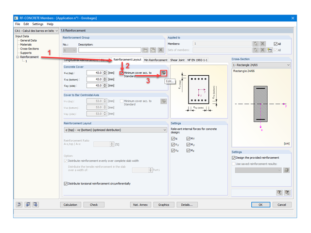
This article deals with the protection of reinforcement against corrosion defined according to EN 1992-1-1, also called concrete cover. The purpose of this article is to show how very many parameters defined in the Eurocodes for concrete reinforcements are considered in the RFEM structural analysis software.
With RF-PUNCH Pro, the punching shear design can be performed according to 6.4, EN 1992-1-1. In the following example, the design according to DIN EN 1992-1-1 will be presented first with automatic design of the inner and outer perimeters and then on the basis of the inner perimeters defined by the user on a simple example.
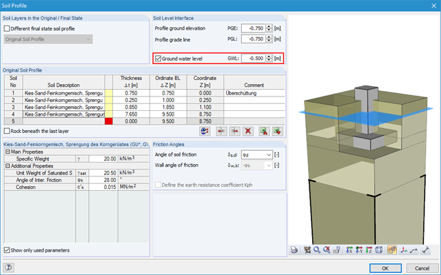
Using RF-/FOUNDATION Pro, it is possible to perform geotechnical design according to EN 1997‑1 [1] for single foundations. Subsequently, the program displays detailed information about the influence of the ground water level on the selected design according to EN 1997‑1.

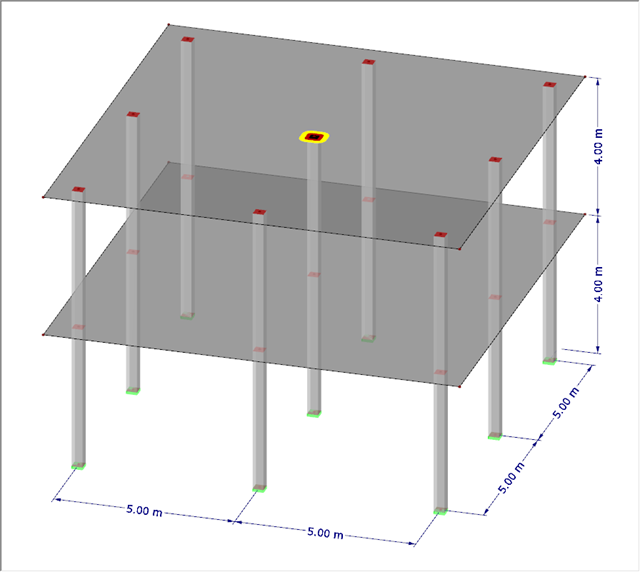
This article describes how a flat slab of a residential building is modeled in RFEM 6 and designed according to Eurocode 2. The plate is 24 cm thick and is supported by 45/45/300 cm columns at distances of 6.75 m in both the X and Y directions (Image 1). The columns are modeled as elastic nodal supports by determining the spring stiffness based on the boundary conditions (Image 2). C35/45 concrete and B 500 S (A) reinforcing steel are selected as the materials for the design.
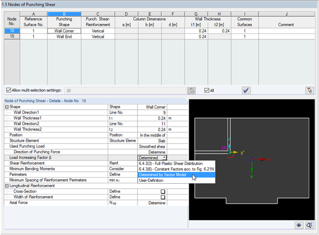
The RF-PUNCH Pro add-on module allows you to perform punching shear designs according to EN 1992‑1‑1 [1]. In addition to the design checks of single columns, wall ends and wall corners can be analyzed in RF‑PUNCH Pro. At this point, I would also like to reference a previous article about RF‑PUNCH Pro, which explains how to determine punching load on wall ends and wall corners.