Canal Bridge Structure over Ems River No. 911 N – Bypass, Germany
Customer Project
-
03
Half-Through Bridge, 3D RFEM Model (© Meyer + Schubart VBI)
-
03
Half-Through Bridge Section View (© Meyer + Schubart VBI)
-
03
Trough Bridge in RFEM (© Meyer + Schubart VBI)
-
03
Deformation under normal water level load case (structure is designed with precamber for permanent loads and normal water level; © Meyer + Schubart VBI)
-
03
Half-Through Bridge, 3D RFEM Model (© Meyer + Schubart VBI)
-
04
Deformation under normal water level load case (structure is designed with precamber for permanent loads and normal water level; © Meyer + Schubart VBI)
-
04
Half-Through Bridge, 3D RFEM Model (© Meyer + Schubart VBI)
-
04
Half-Through Bridge Section View (© Meyer + Schubart VBI)
-
04
Trough Bridge in RFEM (© Meyer + Schubart VBI)
-
04
Half-Through Bridge, 3D RFEM Model (© Meyer + Schubart VBI)
-
05
Half-Through Bridge Section View (© Meyer + Schubart VBI)
-
05
Half-Through Bridge, 3D RFEM Model (© Meyer + Schubart VBI)
-
05
Trough Bridge in RFEM (© Meyer + Schubart VBI)
-
05
Deformation under normal water level load case (structure is designed with precamber for permanent loads and normal water level; © Meyer + Schubart VBI)
-
05
Half-Through Bridge, 3D RFEM Model (© Meyer + Schubart VBI)
The Ems Canal Bridge (KBr), built in the 1930s, will be renovated at DEK-km 78.806N as part of the German Dortmund-Ems Canal (DEK) expansion effort. A double half-through bridge is planned for the new structure, where construction will begin while the shipment is in progress.
Owner |
Federal Waterways and Shipping Agency, WNA Datteln, Germany wna-datteln.wsv.de |
Structural Design, Superstructure Planning Execution |
Meyer + Schubart VBI, Wunstorf, Germany www.meyer-schubart.de
|
Steel Superstructure Execution |
SEH Engineering GmbH, Hanover, Germany www.seh-engineering.de |
Model Parameters
Model
At the beginning of the renovation, a bypass route will be constructed: The longitudinal insertion of the half-through bridge into the bypass location took place in October 2020. The bridge will be moved to its final position after the second section is complete.
Dlubal's customer Meyer+Schubart from Wunstorf (Germany) provided the structural design as well as the superstructure execution planning. The entire steel superstructure was modeled and designed as a 3D model in RFEM, using planar shell elements.
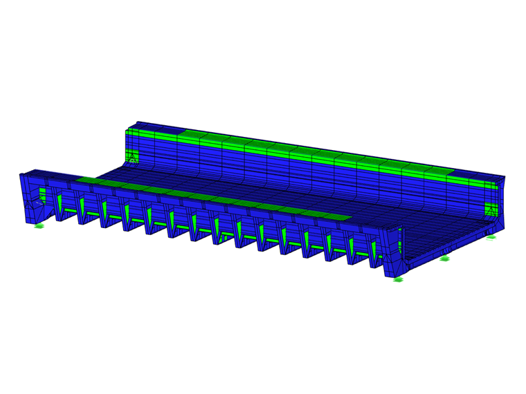
Structure
The half-through bridge spans 205 ft with a total width of 118 ft. It is supported on 108-foot-wide, 22-foot-thick and 18-foot-high abutments. Three spherical supports are provided for each support. In the water-filled operating state, support forces of up to 7,870 kips act on the outer supports.
Between the tail units, the navigable width is 85 ft and the hydraulic width is 92 ft. On the sides (top of the barrier walls) are 16-foot-wide (east side) and 10-foot-wide (west side) service paths. The bridge bottom forms the bottom chord and the service paths form the cross-section top chord for the structural design.
For the design of the canal bridge, variable actions such as hydrostatic + hydrodynamic actions, ice load + ice pressure, temperature, as well as extraordinary actions such as disaster vessel impact (vessel impact with a 6° approach angle), and a sunken vessel load were applied. The structure is designed for 100 years of service life, according to Eurocode.
Literature
Project Location
Keywords
Canal bridge Ems Trough bridge Steel
Write Comment...
Write Comment...
Contact Us
Do you have further questions or need advice? Contact us via phone, email, chat, or forum, or search the FAQ page, available 24/7.
-
The load distribution on my members looks different when using the Load Transfer surface vs. the Load Wizards. What is the reason?
- I received an error message “Surface of incompatible type... (Surface in upper plane of building story must be of ‘Load transfer’ type)” when running the calculation. What is the reason?
- My beam has a continuous lateral support and therefore lateral torsional buckling (LTB) is not a concern. How do I define the effective length?
- How can I efficiently define line hinges on several surfaces?
- How do I include the overstrength factor(s) Ωo in the ASCE 7 load combinations?
- How do I include the redundancy factor(s) ρ in the ASCE 7 load combinations?
- My live load is less than or equal to 100 psf. How do I consider the reduced load factor in the ASCE 7 load combinations?
- I do not see the seismic load cases in my generated ASCE 7 load combinations (COs). How do I add them?
- How do I create an imperfection based on a mode shape in RFEM 6?