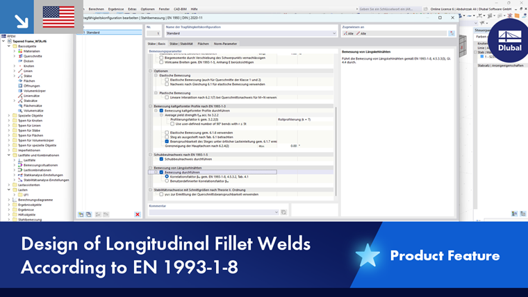
In the Members | Main tab of the "Ultimate Configuration" or "Strength Configuration" dialog box, you can make various settings for the design of members and member sets.
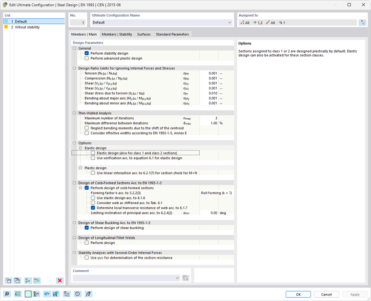
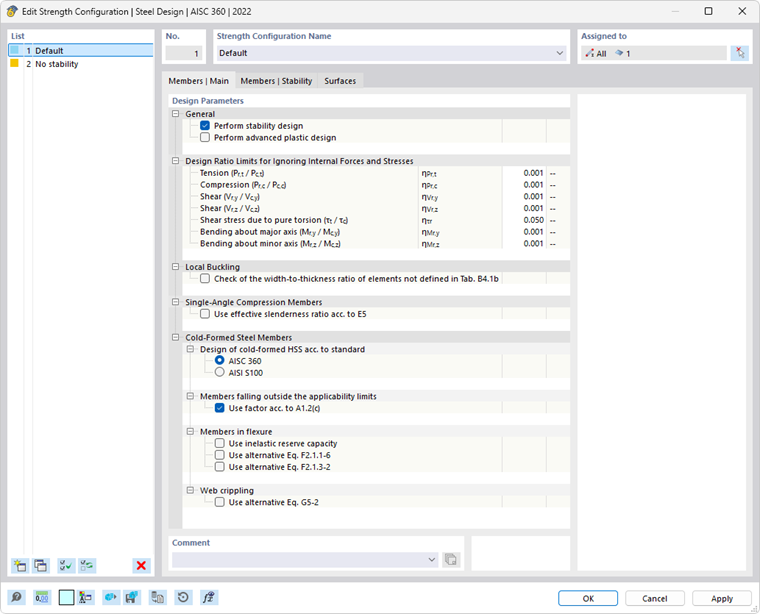
The “Design parameters” are divided into several categories, which differ depending on the design standard.
General
The "Perform stability design" check box controls whether stability design checks, such as against flexural buckling or lateral-torsional buckling, are carried out in addition to the cross-section design checks. Deactivate this check box if you do not want to perform the stability design or if you have already considered the stability effects in the internal forces determination (for example, a calculation according to the second-order or large deformation analysis with imperfections and/or stiffness reduction).
If the stability design is activated, it is necessary to specify effective lengths or boundary conditions for the respective members or member sets. If this is not the case, no stability analysis is possible. After the calculation, a corresponding message appears in the result table of Errors & Warnings. Cable members and tension members are excluded from this, as they can only absorb tensile forces and do not require stability analysis.
The “Perform advanced plastic design” check box provides the option to design members or member sets using the partial internal forces method. You can specify the parameters in the Members | Plasticity tab, which becomes available after you select the option.
Design Ratio Limits for Ignoring Internal Forces and Stresses
The design standards, which are often based on a manual calculation, often only allow design formulas or interaction conditions for certain combinations of internal forces. However, when calculating the structural design using a 3D model, the values for internal forces are usually very small. Although these are insignificant from an engineering point of view in terms of load-bearing capacity, if the design standard is strictly adhered to, they prevent certain design checks or force the use of less favorable interaction formulas. Therefore, the Design Ratio Limits option provides a simple and transparent way of neglecting certain internal forces in the design in order to avoid the problems mentioned above.
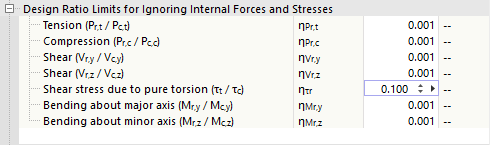
The limit value η describes the ratio of the effective internal force to the plastic section resistance, which is determined in a simplified way via the cross-section properties. These are not design resistances regulated in a standard, so no standard-specific regulations (for example, for cross-section classification) are taken into account, as this does not correspond to the purpose of the limit value setting. Therefore, you should only use high limit values for testing purposes.
If an internal force is below the limit value condition, the design is performed without a warning that the internal force is neglected. In Design Check Details, however, the comment "Negligible" next to the respective internal force allows you to easily check which internal forces have been neglected due to the limit value settings and not considered in the design. If all internal forces are negligible at one location, the design check of the negligible internal forces is specified as design.
.png?mw=760&hash=871be50088766cea03d88f5498092cbe78d1e209)
If you have activated the Torsional Warping (7 DOF) add-on, a limit value for the bimoment and the shear stresses due to the secondary torsion is also available for some design standards.
Analysis of Thin-Walled Structures (for EN)
Determining the effective cross-section requires an iterative procedure. In the “Maximum number of iterations” input box, you can specify the maximum number of calculation runs. As soon as the “Maximum difference between iterations” between the results of two iterations is not exceeded, the calculation ends.
For non-doubly symmetric, cross-sections subjected to compression that are locally prone to buckling, the center of gravity of the effective cross-section is displaced compared to the gross cross-section. The external compressive force acting centrally on the gross cross-section now acts eccentrically on the effective cross-section, resulting in an additional bending moment. This bending moment is taken into account in the calculation by default. If this is not desired, select the “Neglect bending moments due to shift of the centroid” check box.
The “Consider effective widths according to EN 1993-1-5[5], Annex E” check box allows you to control whether the alternative method specified in Annex E for determining the effective cross-section for stresses below the yield stress should be used.
Options (for EN, CSA, GB, SIA, etc.)
Depending on the design standard, additional options are available in the ultimate configuration. They are presented for selected standards.
EN 1993

Cross-sections of Classes 1 and 2 may be designed plastically. Select the “Elastic design (also for class 1 and 2 sections)” check box if these cross-sections are to be designed without using the plastic reserves. In this case, you can use the “Use verification acc. to [1] equation 6.1 for elastic design” check box to control whether the general design should be performed according to elasticity theory. This can be conservative, as no partially plastic stress redistributions are taken into account, which are normally allowed in elastic design.
For plastic design, the “Use linear interaction acc. to 6.2.1(7) for section check for M+N” check box allows you to add the design ratios of the internal forces linearly. This approach is conservative and not allowable for class 4 cross-sections.
CSA S16
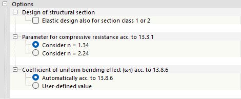
Cross-sections of Classes 1 and 2 may be designed plastically. Select the “Elastic design also for section class 1 or 2” check box if these cross-sections are to be designed without using plastic reserves.
The other options allow you to control the “Parameters for compressive resistance acc. to 13.3.1” and the “Coefficient of uniform bending effect (ω1) acc. to 13.8.6”.
GB 50017
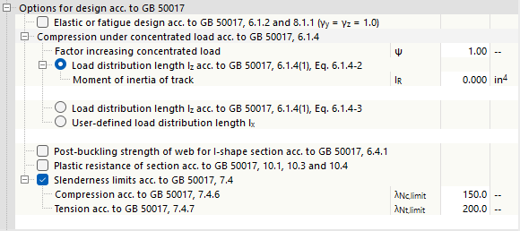
The description is currently being prepared.
SIA 263

The shear force design is usually performed using the effective shear area Av>. For double-symmetrical I-sections and U-sections of cross-section class 3, the web area Aw can also be used as an alternative. To do this, select the “Consider shear area acc. to 5.2.4” check box.
The “Consider shear buckling design” option is activated by default. This means that the shear buckling design is performed according to Sections 4.5.4, 5.3.4, and Appendix F.1. If you deactivate the check box, shear buckling is not analyzed.
Cross-sections of cross-section Class 3 may be designed under bending about both axes with axial force according to Section 5.2.6. If you select the “Use alternative calculation of bending exponents α and β acc. to 5.1.6.4” check box, the design checks for these cross-sections are performed according to Section 5.1.6.4.
Local Buckling (for AISC)

Table B4.1b [2] specifies the width-to-thickness ratios for compression members (cross-section parts) of members subjected to bending. If you design cross-sections that are not covered in this table, select the check box. You can then specify the limit values λr for both unstiffened and stiffened members.
Single-Angle Compression Members (for AISC)
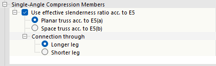
The compressive strength of single-angle cross-sections shall be determined for flexural buckling according to Section E3 or E7, and for flexural-torsional buckling according to Section E4. The “Use effective slenderness ratio acc. to E5” check box provides the option to use the simplified design method according to Section E5, where angles are treated as axially loaded members by adjusting the slenderness ratio. It can be applied when the longitudinal compressive force is applied to one leg. It is necessary to fix the other leg to the adjacent structural component by welding or by a bolted connection with at least two bolts. The calculation of the effective slenderness ratio can be performed either for a “Planar truss acc. to E5(a)” or for a “Spatial truss acc. to E5(b)”.
The method described in Section E5 allows the use of unequal leg lengths connected by the shorter leg, provided that the equivalent slenderness is increased by an amount that takes into account the ratio of the longer to the shorter leg length. Specify whether you want to have the “Connection through” the longer or shorter leg.
Design of Cold-Formed Sections (for EN, AISC, CSA)
For some design standards, it is possible to design cold-formed sections. These are presented for selected standards.
EN 1993
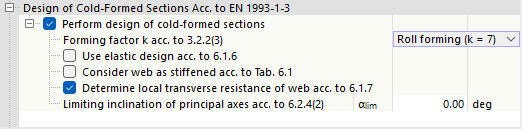
The “Perform design of cold-formed sections” check box is selected by default. Members with such cross-sections are then designed according to EN 1993-1-3 [4]. If you clear the check box, the cold-formed sections are designed according to EN 1993-1-1.
The “Forming factor k acc. to 3.2.2(3)” affects the calculation of the increased yield stress fya. You can select the method used to produce the cross-section. The list provides two options:
- Roll profiling (k = 7)
- Other profiling methods (k = 5)
If you select the “Use elastic design acc. to 6.1.6” check box, the stress checks are performed as specified for torsion in [4], Section 6.1.6. This means that the elastic stress formulas (6.11a), (6.11b) or (6.11c) are used for all combinations of internal forces. More efficient plastic design method, which may be used for certain internal force configurations, is excluded in this case.
If you activate the “Consider web as stiffened acc. to Table 6.1” check box, the web’s resistance under local load introduction is not determined. No local buckling can occur.
The “Determine local transverse resistance of web acc. to 6.1.7” check box controls whether the design checks for local compressive stress, web crippling, or local buckling in the web are performed. The requirement for this is that a corresponding design support is defined.
The lateral-torsional buckling analysis for structural components subjected to bending is not applicable according to EN 1993-1-3, Section 6.2.4(2) if the cross-section has a significant angle difference between the principal axes of the effective cross-section and the principal axes of the gross cross-section. You can use the input box for the “Limiting inclination of principal axes acc. to 6.2.4(2)” to specify the angle αlim up to which the design is still performed.
AISC 360
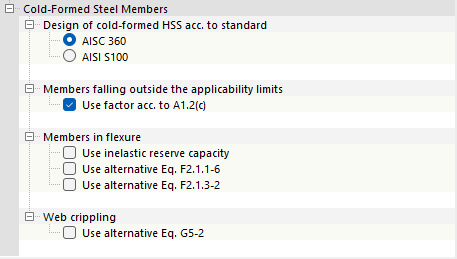
Specify whether the “Design of cold-formed HSS acc. to standard” should be based on AISC 360 or AISI 100.
For “Members failing outside the applicability limits” of the AISI table B4.1-1, you can use the check box to specify whether the safety factor Ω or the resistance factor Φ according to AISI S100, Section A1.2(c) should be applied. This specification also applies to general cross-sections whose application limits are not regulated in the standard.
The check boxes in the “Members in flexure” category allow you to specify details for stability analysis. This makes it possible to use the inelastic reserve capacity according to AISI sections F2.4.2, F3.2.3, and F4.3. For double-symmetrical I-sections, the elastic buckling stress Fcre can alternatively be determined according to Eq. (F2.1.1-6). If point-symmetrical Z-sections are analyzed, it is also possible to determine Fcre according to Eq. (F2.1.3-2).
The strength Pn against “web crippling” is determined according to Eq. (G5-1). Alternatively, the value can be determined according to Eq. (G5-2). To do so, select the corresponding check box.
CSA S16
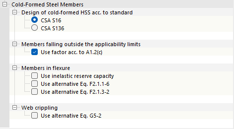
Specify whether the “Design of cold-formed HSS acc. to standard” CSA S16 or CSA S136 should be used.
For “Members failing outside the applicability limits” of [3] Table B4.1-1, you can use the check box to specify whether the safety factor Ω or the resistance factor Φ should be applied according to [3], Section A1.2(c). This specification also applies to general cross-sections whose application limits are not regulated in the standard.
The check boxes in the “Members in flexure” category allow you to specify details for stability analysis. This makes it possible to use the inelastic reserve capacity according to [3], Sections F2.4.2, F3.2.3, and F4.3. For double-symmetrical I-sections, the elastic buckling stress Fcre can alternatively be determined according to Eq. (F2.1.1-6). If point-symmetrical Z-sections are analyzed, it is also possible to determine Fcre according to Eq. (F2.1.3-2).
The strength Pn against “web crippling” is determined according to Eq. (G5-1). Alternatively, the value can be determined according to Eq. (G5-2). To do so, select the corresponding check box.
Shear Buckling Design (for EN)

The “Perform design of shear buckling” check box is activated by default. It checks whether the slenderness ratio λ of the web requires a shear buckling design according to [5], Sections 5.1, 5.2, 5.3, and 5.5. If the limit value λlim is met, the design is considered fulfilled. However, if the slenderness is above the limit value according to Section 5.1. (2), member transverse stiffeners are provided at the supports in order to enable the shear buckling design to be carried out.
Design of Longitudinal Fillet Welds (for EN, AISC, CSA)
For some design standards, it is possible to design longitudinal fillet welds. The options are presented for selected standards.
EN 1993

If you want to design the load-bearing capacity of the longitudinal welds of welded cross-sections, select the “Perform design” check box. The factor βw is stored as a material property for most steel materials in the library according to EN 1993-1-8, Table 4.1. If the cross-section parts are made of different steel grades, you can also specify the correlation factor βw for the design of fillet welds.
AISC 360
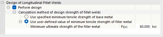
For structural components with welded cross-sections, the longitudinal fillet welds between the web and flange may be designed according to [2] Section J2.4. The design strength of the welds can be determined using two methods.
- Minimum tensile strength of the base metal: Only the base metal of the plate is tested.
- User-defined minimum tensile strength of the filler material: Both the base metal of the plate and the welding filler material are tested.
CSA S16
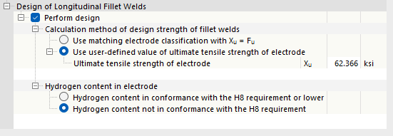
For structural components with welded cross-sections, the longitudinal fillet welds between the web and the flange may be designed according to [3], Section 13.13.2.2. The design strength of the welds can be determined using two methods.
- Matching electrode classification Xu = Fu: When using a matching electrode according to CSA W59-18, Table 11.1 or Table 12.1, it is assumed that the tensile strength of the electrode Xu is higher than the tensile strength of the base metal Fu. For simplicity, therefore, Xu = Fu is assumed.
- User-defined ultimate tensile strength of the electrode: When using a matching electrode according to CSA W59-18, Table 11.1 or Table 12.1, or a non-matching electrode, the ultimate tensile strength can be specified manually. However, when using an oversized electrode, the value of Xu, according to [3] Section 13.13.2.2, must not exceed the value of Xu for the suitable electrode.
The hydrogen content in the electrode also plays a role in the design. Specify whether the hydrogen content meets or is below the requirement H8. If this is the case, the material thickness t used to determine Smin corresponds to the thickness of the thinner connected cross-sectional part. For electrodes certified without a designation for diffusible hydrogen, or those whose hydrogen content exceeds the requirements for H8, the material thickness t corresponds to the thickness of the thicker part.
Stability Analysis with Internal Forces According to Second-Order Analysis (for EN)

It is possible to perform stability analysis using second-order analysis, internal forces, taking into account warping torsion and imperfections, instead of the equivalent member method according to [1], Section 6.3. In this case, you can select the “Use γM1 for determination of the section resistance” check box to control whether the coefficient γM1 (instead of γM0) is used for the cross-section checks.