In the Main tab of the "Serviceability Configuration" dialog box, you can set the limits applicable to the deformations of members and member sets.


The "Design Parameters" are subdivided into categories. They differ depending on the design standard.
Serviceability Limits
There are different design situation types for serviceability limit state design checks (see the chapter Design Situations of the RFEM manual). For example, the design according to EN 1993-1-1 distinguishes between the characteristic, frequent, and quasi-permanent combination. Four types are preset for AISC 360: The first limit state is of a general nature and applies to all load combinations. The other three types are based on the IBC standard [1]. For each type of combination, you can define specific limit values of deflections that apply to the directions of the member axes.
In principle, the limit values for the deformations are related to the lengths of the structural components: The longer a member is, the greater deflections are allowable. In the list next to the “Definition type”, you can select how you want to define the limit value.
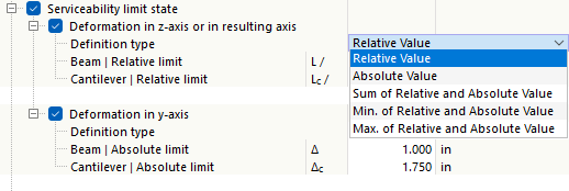
- Relative Value: The limit value is defined related to the length of the member or member set.
- Absolute Value: The value of the maximum deflection is defined directly.
- Sum of Relative and Absolute Value: The limit value is the sum of the relative value and the absolute value.
- Min. of Relative and Absolute Value: The lower of the relative or absolute value is used as the limit value.
- Max. of Relative and Absolute Value: The limit value is the larger of the relative or absolute value.
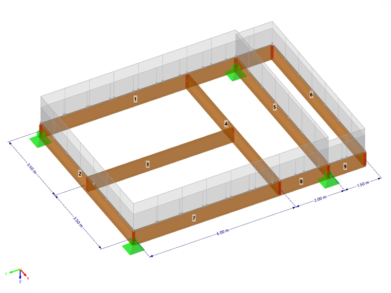
Depending on the support of the structural component- a “beam” supported on both sides or a “cantilever” supported on one side—different deflection limit values are usually relevant. The type that exists for a particular segment is automatically determined on the basis of the assigned design supports: A segment with design supports on both sides or without design supports is classified as a beam, a segment with a design support on one side is classified as a cantilever. You can define the design supports in the Design Supports and Deflection tab of the members and member sets.
If necessary, adjust the preset limits for the deformation analyses of the objects.
If a precamber (pre-deformation of the structural component during assembly) is to be taken into account in the deformation analysis, you can specify this initial bow in the properties of the member or member set (see the chapter Design Supports and Deflection). There you can also specify whether the maximum displacements refer to the shifted segment ends or the undeformed initial system.
Vibration (for EN, NTC)
The “Vibration” category allows for a simple check of the deformation for the vibration analysis with reference to a vibration amplitude. This design takes into account all design situations with the SLS – Vibration type assigned in the Design Situations table. It is assumed that these are corresponding load combinations or result combinations that contain the maximum values of the vibration amplitudes in the form of deflections. They are compared with the limit value in the respective axis direction.
Limitation of Web Breathing (for EN, NTC)
For the frequent SLS combination of steel bridges, the web slenderness can be checked according to EN 1993-2 [[#Refer [2]]] 7.4. This slenderness ratio is governing as to whether “plate breathing” occurs in the form of alternating bending from the plate plane. This can result in fatigue problems at the web-flange connections.
Specify whether a “road bridge” or “railroad bridge” is present. The program then sets the corresponding limit value. If Member Transverse Stiffeners are assigned to the object to be designed and these are activated for the design add-on, the distances between the transverse stiffeners are used for the design of the web breathing. The segment length Lc, which is defined in the member properties in the Design Supports and Deflection tab, is used as the reference length for the design.