A rib element can easily be modeled in RFEM 6 by changing the Member Type from "Beam" to "Rib" in the drop-down shown in Image 01.
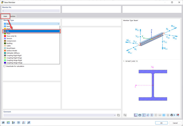
Then, once a section and material is assigned in the Section tab, a new tab called "Rib" can be used to change a multitude of parameters.
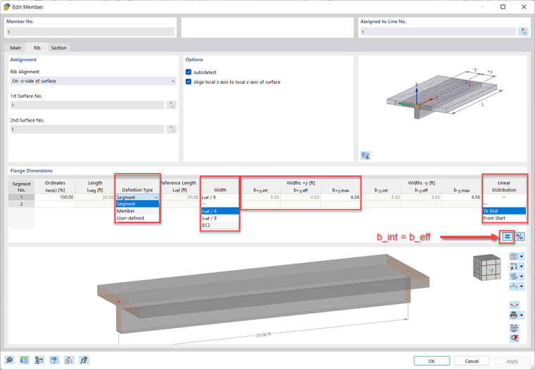
Under the "Rib" tab, the rib alignment can be chosen along with one or two surfaces the rib is integrated with. Then, segments can be created using percentage (default) or lengths under the Ordinates column. These two options can be swapped by using the "Switch Relative/Absolute Ordinates" or "%" button. Segments allow you to divide the member and use different parameters for each section. That length is referenced in the next list of parameters.
The first parameter is the Definition Type where you can choose if you would like to adjust a Segment, Member, or User-Defined. User-Defined allows you to enter a custom length for Lref/8. Choosing member sets Lref to the length of the member. Segment sets Lref to the length of the segment.
Then, the "Width" parameters can either be entered manually, or they can be determined by referencing the length or EC2. These options can be seen in Image 02 along with the following parameters. Here are their definitions:
| bint | Internal integration width of the surface |
| beff | Effective width used in the Concrete Design add-on |
| bmax | Maximum possible value for bint and beff |
If the equal sign "=" button is selected, then beff will be set equal to bint.