194 Wyniki
Wyświetl wyniki:
Sortuj według:

Płyta kompaktowa (CD) obraca się z prędkością 10 000 obr./min. Dlatego jest poddawany działaniu siły odśrodkowej. Problem jest zamodelowany jako ćwiartka. Należy określić naprężenie styczne σt na średnicy wewnętrznej i zewnętrznej oraz ugięcie promieniowe ur promienia zewnętrznego.

Konstrukcja składa się z swobodnie podpartej belki o przekroju dwuteowym. Obrót osiowy φx jest ograniczony na obu końcach, ale przekrój może ulec deplanacji (podpora widełkowa). Belka posiada początkową imperfekcję w kierunku Y zdefiniowaną jako krzywa paraboliczna o maksymalnym przemieszczeniu 30 mm w środku. Obciążenie równomierne zostaje przyłożone w środku górnego pasa profilu dwuteowego. Problem opisano za pomocą poniższego zestawu parametrów. Przykład obliczeniowy oparty jest na przykładzie wprowadzonym przez Gensichen i Lumpe.

Konstrukcja składa się z belki o przekroju dwuteowym i dwóch kratownic rurowych. The structure contains several imperfections and it is loaded by the force Fz. Ciężar własny jest pomijany w tym przykładzie. Determine the deflections uy and uz and axial rotation φx at the endpoint (Point 4). Przykład obliczeniowy oparty jest na przykładzie wprowadzonym przez Gensichen i Lumpe.

W tym przykładzie weryfikacyjnym sprawdzana jest nośność wewnętrznego słupa płyty płaskiej na ścinanie. Słup ma przekrój kołowy o średnicy 30 cm.
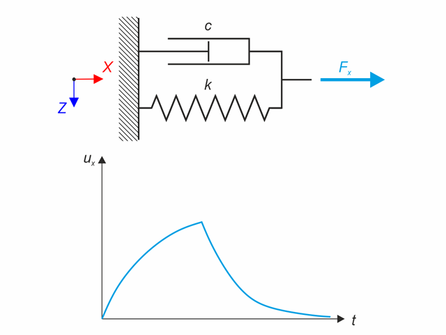
Model materiałowy Kelvina-Voigta składa się z równolegle połączonych sprężyny liniowej i amortyzatora wiskotycznego. W tym przykładzie weryfikacyjnym sprawdzane jest zachowanie tego modelu w czasie przy obciążeniu i relaksacji w przedziale czasowym 24 godzin. Stała siła Fx jest stosowana przez 12 godzin, a pozostałe 12 godzin to model materiałowy bez obciążenia (relaks). Oceniane jest odkształcenie po 12 i 20 godzinach. Wykorzystano analizę historii czasowej metodą liniową niejawną metodą Newmarka.
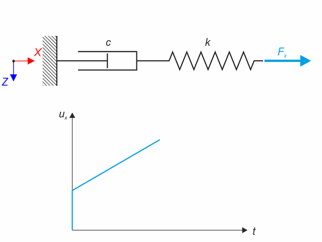
Model materiałowy Maxwell składa się z szeregowo połączonych sprężyny liniowej i amortyzatora wiskotycznego. W tym przykładzie weryfikacyjnym sprawdzane jest zachowanie się modelu w czasie. Model materiałowy Maxwella jest obciążony stałą siłą Fx. Siła ta powoduje początkowe odkształcenie sprężyny, a następnie odkształcenie narasta w czasie dzięki tłumikowi. Odkształcenie jest obserwowane w momencie obciążenia (20 s) i na końcu analizy (120 s). Wykorzystano analizę historii czasowej metodą liniową niejawną metodą Newmarka.

Zaplanowano dach z określoną geometrią zawartą w projekcie na dużych powierzchniach w połączeniu z zaawansowanymi metodami RFEM 6 i RFEM 6, które zostały zaprojektowane ręcznie. Został wprowadzony 3 Lastsysteme untersucht.
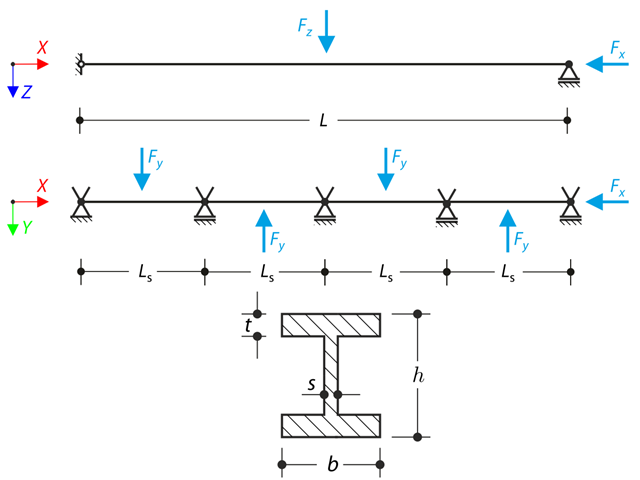
Belka ciągła z czterema przęsłami jest obciążona siłami osiowymi i zginającymi (zastępuje imperfekcje). Wszystkie podpory są widełkowe - deplanacja jest dowolna. Określ przemieszczenia uy i uz, momenty My, Mz, Mω i MTpri oraz obrót φx. Przykład obliczeniowy oparty jest na przykładzie wprowadzonym przez Gensichen i Lumpe.
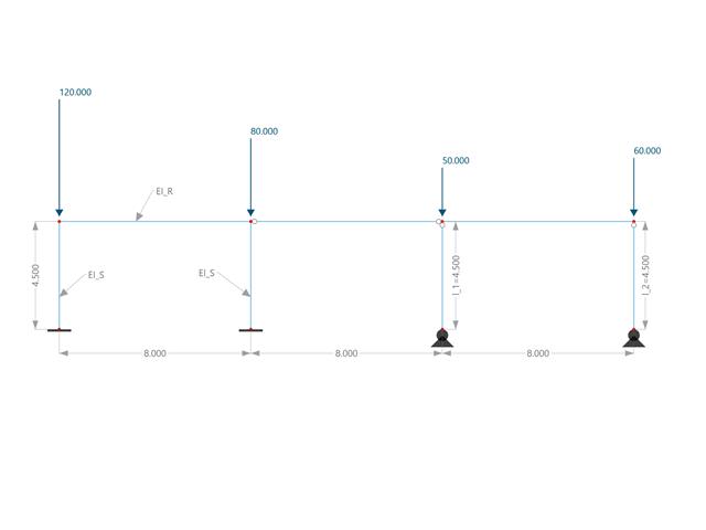
W tym przykładzie porównuje się długości efektywne i współczynnik obciążenia krytycznego, które mogą być obliczone w programie RFEM 6 przy użyciu rozszerzenia Stateczność konstrukcji, z obliczeniami ręcznymi. Układ konstrukcyjny stanowi sztywna rama z dwoma dodatkowymi słupami przegubowymi. Ten słup jest obciążany pionowymi obciążeniami skupionymi.
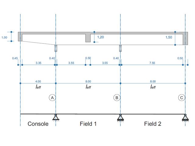
Belka żelbetowa została zaprojektowana jako belka dwuprzęsłowa na wsporniku. Przekrój zmienia się na całej długości wspornika (przekrój o zmiennym przekroju). Obliczane są siły wewnętrzne oraz wymagane zbrojenie podłużne i zbrojenie na ścinanie dla stanu granicznego nośności.
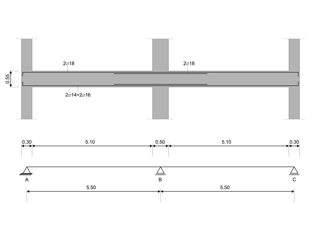
W tym przykładzie obliczeniowym obliczane są wartości nośności sił tnących na belkach zgodnie z EN 1998-1, 5.4.2.2 i 5.5.2.1 oraz nośność słupów przy zginaniu zgodnie z 5.2.3.3(2 ). System składa się z dwuprzęsłowej belki żelbetowej o rozpiętości 5,50 m. Belka jest częścią układu ramowego. Otrzymane wyniki są porównywane z wynikami w [1].
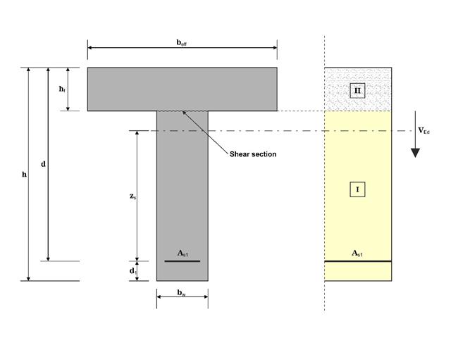
W tym przykładzie ścinanie na granicy między betonem wylanym w różnym czasie a odpowiednim zbrojeniem jest określane zgodnie z DIN EN 1992-1-1. Wyniki uzyskane w programie RFEM 6 zostaną porównane z poniższymi obliczeniami ręcznymi.
Obrót osiowy profilu dwuteowego jest ograniczony na obu końcach za pomocą podpór widełkowych (nieograniczona deplanacja). W środku konstrukcja jest obciążona dwiema siłami poprzecznymi. Ciężar własny jest pomijany w tym przykładzie. Określ maksymalne ugięcia konstrukcji uy,max i uz,max, maksymalny obrót φx,max, maksymalne momenty zginające My,max i Mz,max i maksymalne momenty skręcające MT,max, MTpri,max, MTsec,max i Mω,max. Przykład obliczeniowy oparty jest na przykładzie wprowadzonym przez Gensichen i Lumpe.
Pręt o zadanych warunkach brzegowych jest obciążony momentem skręcającym i siłą osiową. Pomijając ciężar własny, należy określić maksymalne odkształcenie skręcające belki' oraz jej wewnętrzny moment skręcający, zdefiniowany jako suma głównego momentu skręcającego i skręcającego wywołanego siłą normalną. Należy porównać te wartości, przyjmując lub pomijając wpływ siły normalnej. Przykład obliczeniowy oparty jest na przykładzie wprowadzonym przez Gensichen i Lumpe.
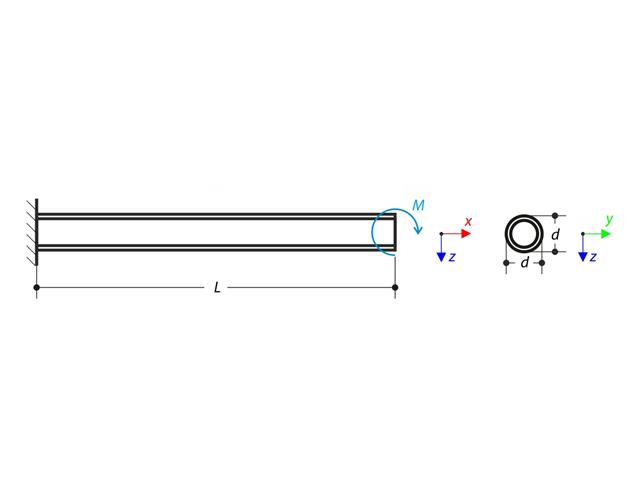
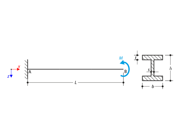
Wspornik jest obciążony momentem na jego wolnym końcu. Korzystając z analizy geometrycznej liniowej i analizy dużych deformacji oraz pomijając ciężar własny belki, należy określić maksymalne ugięcia na swobodnym końcu. Przykład obliczeniowy oparty jest na przykładzie wprowadzonym przez Gensichen i Lumpe.
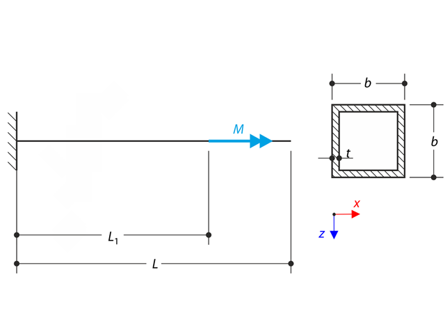
Cienkościenny wspornik profilu QRO jest w pełni zamocowany na lewym końcu, a deplanacja jest wolna. Wspornik jest poddany skręcaniu. Uwzględniane są niewielkie odkształcenia, a ciężar własny jest pomijany. Określ maksymalny obrót, moment główny, moment drugorzędny i moment deplanacyjny. Przykład obliczeniowy oparty jest na przykładzie wprowadzonym przez Gensichen i Lumpe.
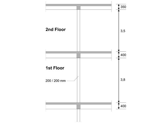
W pierwszym piętrze budynku zaprojektowano słup wewnętrzny. Słup jest monolityczny, połączony z belką górną i dolną. Uproszczona metoda A obliczeń odporności ogniowej dla słupów zgodnie z EC2-1-2 została potwierdzona, a wyniki porównane z [1].
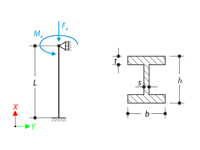
Belka jest w pełni utwierdzona (skrętność jest ograniczona) na lewym końcu i podparta na podporze widełkowej (swobodna deplanacja) na prawym końcu. Belka jest poddawana działaniu momentu obrotowego, siły podłużnej i siły poprzecznej. Zdefiniuj zachowanie głównego momentu skręcającego, drugorzędnego momentu skręcającego i momentu skrępowanego. Przykład obliczeniowy oparty jest na przykładzie opracowanym przez Gensichen i Lumpe (patrz odniesienie).
Wspornik o profilu dwuteowym jest podparty na lewym końcu i jest obciążony momentem obrotowym M. Celem tego przykładu jest porównanie podpory nieruchomej z podporą widełkową i zbadanie zachowania się niektórych reprezentatywnych wielkości. Przeprowadzane jest również porównanie z rozwiązaniem za pomocą płyt. Przykład obliczeniowy oparty jest na przykładzie wprowadzonym przez Gensichen i Lumpe.
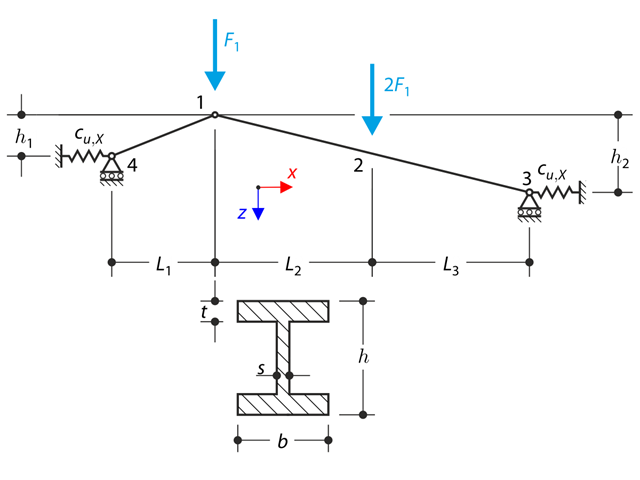
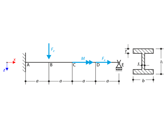
Konstrukcja wykonana z kratownic o profilu dwuteowym jest podparta na obu końcach przez sprężyste podpory ślizgowe i obciążona siłami poprzecznymi. W tym przykładzie pominięto ciężar własny . Należy określić ugięcie konstrukcji, moment zginający, siłę normalną w danych punktach testowych oraz ugięcie poziome podpory sprężystej.
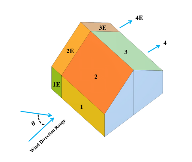
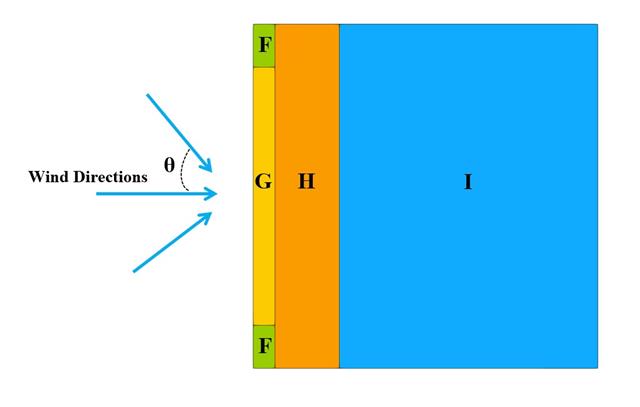
W bieżącym przykładzie walidacyjnym badany jest współczynnik ciśnienia wiatru (Cp) zarówno dla głównych elementów konstrukcyjnych (Cp,ave ), jak i drugorzędnych elementów konstrukcyjnych, takich jak systemy okładziny lub fasady (Cp,local ) w oparciu o NBC 2020 [1] and Baza danych japońskich tuneli aerodynamicznych dla niskiego budynku o nachyleniu 45 stopni. Zalecane ustawienie dla trójwymiarowego dachu płaskiego z ostrym okapem zostanie opisane w następnej części.
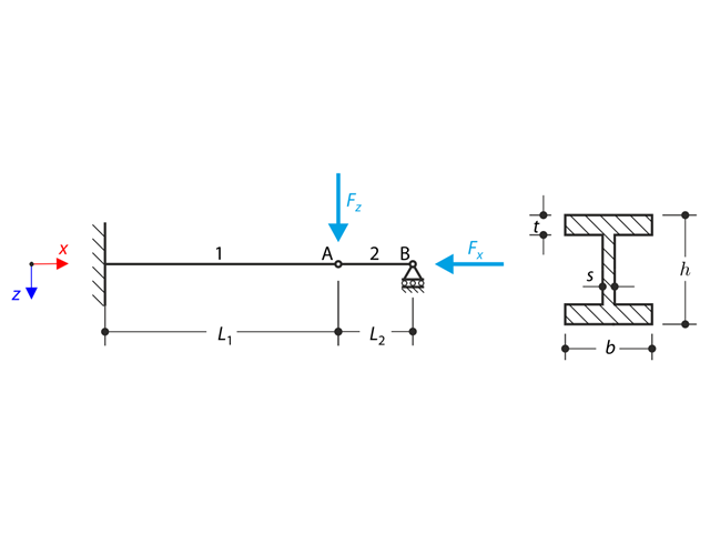
Konstrukcja z profilu I jest w pełni utwierdzona na lewym końcu i osadzona w podporze przesuwnej na prawym końcu. Konstrukcja składa się z dwóch segmentów. Ciężar własny jest pomijany w tym przykładzie. Określ maksymalne ugięcie konstrukcji uz,max, moment zginający My na nieruchomym końcu, obrót &2,y segmentu 2 oraz siły reakcji RBz za pomocą analizy geometrycznie liniowej i analizy drugiego rzędu. Przykład obliczeniowy oparty jest na przykładzie wprowadzonym przez Gensichen i Lumpe.
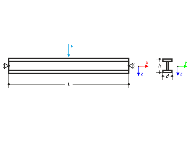
Belka podparta przegubowo na obu końcach jest obciążona siłą poprzeczną w środku. Pomijając ciężar własny i sztywność na ścinanie, należy określić maksymalne ugięcie, siłę normalną i moment w środku rozpiętości, przyjmując teorię drugiego i trzeciego rzędu. Przykład obliczeniowy oparty jest na przykładzie opracowanym przez Gensichen i Lumpe (patrz odnośnik).
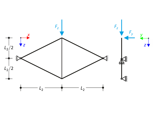
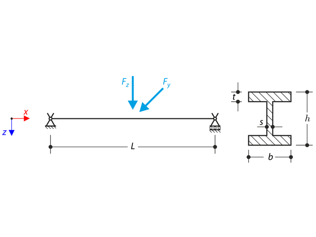
Płaska kratownica składająca się z czterech nachylonych prętów i jednego pręta pionowego jest obciążona w górnym węźle siłą pionową Fz oraz siłą Fy leżącą poza płaszczyzną. Zakładając analizę dużych deformacji i pomijając ciężar własny, należy określić siły normalne prętów oraz przemieszczenie górnego węzła z płaszczyzny uy. Przykład obliczeniowy oparty jest na przykładzie wprowadzonym przez Gensichen i Lumpe.
W poniższym przykładzie sprawdzamy wartość ciśnienia wiatru zarówno dla ogólnego projektowania konstrukcyjnego (Cp,10 ), jak i lokalnego projektowania konstrukcyjnego, takiego jak okładziny lub fasady (Cp,1 ) w oparciu o EN 1991-1-4, przykład dachu płaskiego [1] and Baza danych japońskich tuneli aerodynamicznych . Zalecane ustawienie dla trójwymiarowego dachu płaskiego z ostrym okapem zostanie opisane w następnej części.
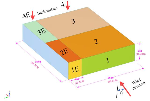
W bieżącym przykładzie walidacyjnym badamy współczynnik parcia wiatru (Cp) płaskiego dachu i ścian za pomocą ASCE7-22 [1]. W rozdziale 28.3 (Obciążenia wiatrem - główny układ odporności na siłę wiatru) i na Rysunku 28.3-1 (przypadek obciążenia 1) znajduje się tabela przedstawiająca wartość Cp dla różnych kątów nachylenia dachu.
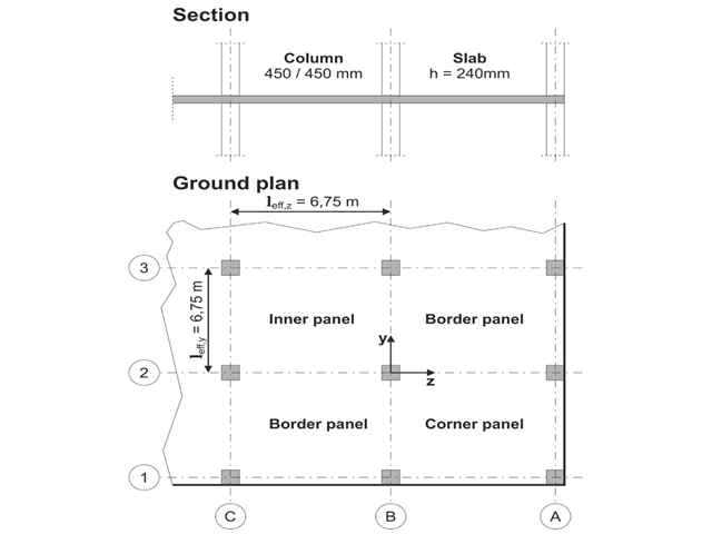
Model oparty jest na przykładzie 4 z [1]: Płyta podparta punktowo.
Należy zaprojektować płaską płytę budynku biurowego o wrażliwych na zarysowania ścianach lekkich. Należy zbadać panele wewnętrzne, brzegowe i narożne. Słupy i płyta są połączone monolitycznie. Słupy skrajne i narożne są zlicowane z krawędzią płyty. Osie słupów tworzą siatkę kwadratową. Jest to układ sztywny (budynek usztywniony ścianami usztywniającymi).
Budynek biurowy ma 5 kondygnacji i ma wysokość 3.000 m. Warunki środowiskowe, które należy przyjąć, określane są jako „zamknięte przestrzenie wewnętrzne”. Występują głównie oddziaływania statyczne.
Celem tego przykładu jest określenie momentów w płycie i wymaganego zbrojenia nad słupami przy pełnym obciążeniu.
Model oparty jest na przykładzie 4 z [1]: Płyta podparta punktowo. Siły wewnętrzne i wymagane zbrojenie podłużne można znaleźć w przykładzie weryfikacji 1022. W tym przykładzie przebijanie jest rozpatrywane w osi B/2.
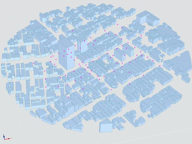
Japoński Instytut Architektury (AIJ) przedstawił kilka dobrze znanych scenariuszy porównawczych symulacji wiatru.
Poniższy artykuł dotyczy "Przypadku E - zespół budynków w rzeczywistym obszarze miejskim o gęstej koncentracji niskiej zabudowy w mieście Niigata".
Poniżej opisany scenariusz jest symulowany w RWIND2, a wyniki są porównywane z symulowanymi i doświadczalnymi wynikami AIJ.
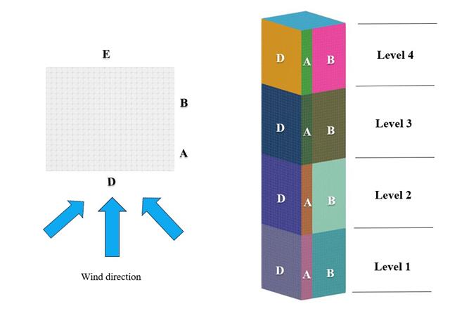
W bieżącym przykładzie walidacji badamy wartość parcia wiatru dla obu ogólnych projektów konstrukcyjnych (Cp,10 ) i okładzin lub elewacji (Cp,1 ) budynków na planie prostokąta zgodnie z EN 1991-1-4 [1]. Istnieją przypadki trójwymiarowe, o których więcej wyjaśnimy w następnej części.