


Member transverse stiffeners can be taken into account in the shear resistance design of web plates in order to limit the buckling panels. Further design checks, for example, for concentrated load introduction into a stiffener, are not performed.
Assignment to Member or Member Set
Member transverse stiffeners are organized in RFEM and RSTAB as a "Type for Members". Thus, you can assign the member transverse stiffeners to one or more members by using the Edit Member dialog box, by selecting them in the Member Transverse Stiffener dialog box, or via the input table. The assignment is done similarly to the procedure described in the chapter Steel Design.
Furthermore, it is possible to assign the member transverse stiffeners to a member set. The relative position of the stiffener types then refers to the length of the entire member set. Note that member transverse stiffeners can be assigned either to a member or to a superordinate member set.
Stiffener Type and Location
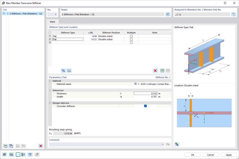
In the Stiffener Type and Position section, specify all stiffener types and their locations. Click the
![]() button to switch between the absolute and the relative input of the position. Click the
button to switch between the absolute and the relative input of the position. Click the
![]() button to sort the list according to the positions.
button to sort the list according to the positions.
The following types are currently available:
- Flat stiffeners
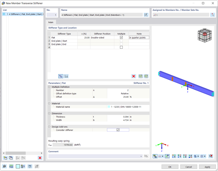
- End plates at the member start and end
- Channel sections
- Angle sections (connection of both legs to the stiffened web)
- Connecting columns at the member start and end
- Warping restraints
Some stiffener types (such as flat stiffeners) require entering the stiffener position (left, right, or double-sided). In this case, the left side means the side lying in the negative y-direction.
Select the "Multiple" check box to add more stiffeners of the same type to a beam. In the parameters, you can now specify the number of stiffeners and the offset recurrence.
Parameters
In this section of the dialog box, you define the main properties of each stiffener type. In most cases, this requires information about the material and dimensions of the stiffener.
To include a stiffener in the design in the add-on, select the "Consider Stiffener in Design Add-ons" check box. Depending on the selected design standard, this option is not available for all stiffener types. It may be necessary to classify the stiffener with regard to its plasticity.
Warping Restraint
If the Torsional Warping (7 DOF) add-on has been activated, the member transverse stiffeners are used to define warping restraints when calculating members with 7 degrees of freedom. More information can be found in the chapter Member Transverse Stiffeners of the manual for this add-on.
If you want to use the member transverse stiffeners for the design in Steel Design, the resulting warping restraints spring stiffness is only displayed as information. There is no automatic transfer to the input windows of nodal supports in the dialog boxes Effective Lengths or Boundary Conditions.