Question
How many divisions must a member have for the calculation in RFEM in order to obtain accurate results?
Answer:
It is not possible to give a general answer to this question, as it depends on the structural system. There are several divisions to be considered in RFEM.
The member divisions for result values can be created via "Insert" → "Model Data" → "Member Divisions". This division ensures that the internal forces of members can also be displayed at intermediate points in the RFEM results tables, for example. The graphical result display remains unchanged.
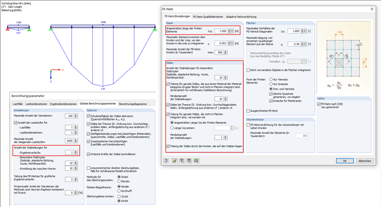
The divisions for the graphical result diagram and the determination of the extreme value can be displayed and controlled in the FE mesh settings (see Image 01).
For cable, foundation, and tapered members or members with plastic properties, you can specify the number of internal divisions. They lead to a real division of the member by intermediate nodes. However, if a member is arranged on the boundary line of a surface or if the definition line has an FE mesh refinement, the specification has no effect.
The option to activate member divisions for large deformation or post-critical analysis allows you also to divide beams for the calculation according to the large deformation analysis by intermediate nodes, so that these members are calculated with higher accuracy. The number of member divisions is taken from the text box above.
When using the division even for straight members, which are not integrated into surfaces, FE nodes are generated on all free members and considered for calculations according to the linear static and the second-order analysis. The FE length is either determined by the global target length lFE in the General section of the dialog box, or entered manually.
With the Use division for members with nodes lying on them option, RFEM creates FE nodes on the locations of the member where end nodes of other members are located, without any connection occurring between these members.
Do you have any questions?
This article describes and explains the influence of bending stiffness of cables on their internal forces. Furthermore, the text provides information on how this influence can be reduced.
Using the Timber Design add-on, timber column design is possible according to the 2018 NDS standard ASD method. Accurately calculating timber member compressive capacity and adjustment factors is important for safety considerations and design. The following article will verify the maximum critical buckling strength calculated by the Timber Design add-on using step-by-step analytical equations as per the NDS 2018 standard including the compressive adjustment factors, adjusted compressive design value, and final design ratio.
In this article, the adequacy of a 2x4 dimension lumber subject to combined biaxial bending and axial compression is verified using the RF-/TIMBER AWC add-on module. The beam-column properties and loading are based on example E1.8 of AWC Structural Wood Design Examples 2015/2018.
In RFEM 5 as well as RSTAB 8 in RF-/FOUNDATION Pro, you can save the foundation dimensions for all five foundation types as foundation templates in a user-defined database and use them later in other models.
The results of solid stresses can be displayed as colored 3D points in the finite elements.
Use the "Independent mesh preferred" option in the FE mesh settings to create an independent FE mesh for the integrated objects. This allows you to generate a significantly more detailed and precise FE mesh for individual objects that are integrated into one another.
In the "Edit Section" dialog box, you can display the buckling shapes of the Finite Strip Method (FSM) as a 3D graphic.
In RFEM 6 and RSTAB 9, you have the option to enter "Visual Objects" as guide objects. You can import the file formats 3ds, stl, and obj.
These objects allow you to create a better reference to the dimensions.
Is it possible to add this new load case to combinations that are generated automatically?
Recommended Products for You