This article explains what influence the selected model in the support area has on internal forces and deformations.
Description of Models A – E
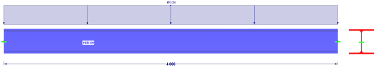
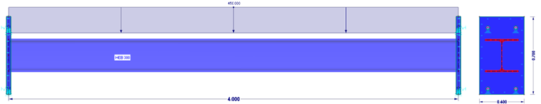
Model A represents the standard case of using a pure member model. The girder is rigid on both sides; all six degrees of freedom are locked. The model does not have any nonlinearities. The member model is supported by nodal supports of the "Rigid" type.
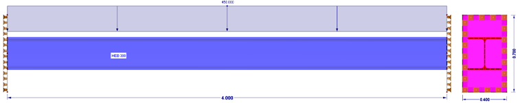
In Model B, the member has a rigid end plate on both sides, which is linearly supported. Rigid means that the plate deformations are not taken into account. The support is modeled as a pure surface support.
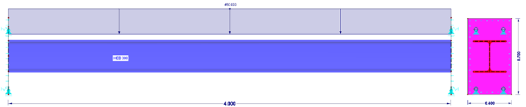
In Model C, the member has a rigid end plate on both sides, which is nonlinearly supported. Only compressive stresses are absorbed in the surface support. Shear and tensile forces are absorbed by nonlinearly defined nodal supports.
In Model D, the member has a finite thick end plate (t = 100 mm) on both sides, which is nonlinearly supported. Only compressive stresses are absorbed in the surface support. Shear and tensile forces are absorbed by nonlinearly defined nodal supports.
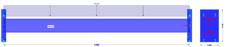
In Model E, the member has a finite thick end plate (t = 40 mm) on both sides, which is nonlinearly supported. Only compressive stresses are absorbed in the surface support. Shear and tensile forces are absorbed by nonlinearly defined nodal supports.
Note for modeling "dowels": In our example, Model C, Model D, and Model E include a nonlinear translational spring in order to transfer the tensile forces.
Evaluation and Comparison of Results
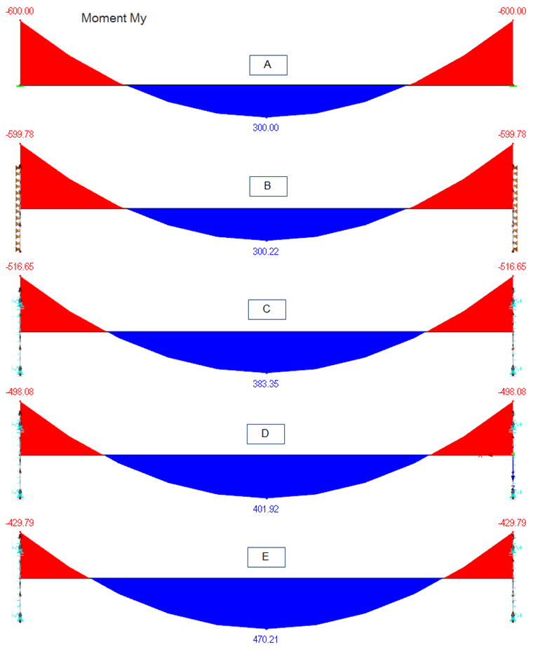
The simple member model (Model A) with rigid restraint shows, as expected, the largest restraining moments and thus the lowest moment in the span. Regarding the design of the end plate and the fastener, this is the most conservative result. However, the moment in the span is undervalued.
Model B shows almost the same results as Model A. The rigid surface with the linear support does not allow for any other results. Such modeling is not reasonable in practice.
In Model C, the nonlinearity shows a clear increase of the moment in the span of 27%, compared to the simple member model. The restraining moment decreases accordingly.
The more realistic the support conditions are, the more the moment in the span increases. Thus, the moment in the span is about 34% higher in Model D than in the simple member model.
The influence of the support conditions is most significant when using the real thickness of the steel plate. In this case, the moment in the space is increased by 56%, as you can see in Model E.
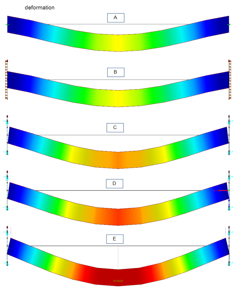
The deformations are also important boundary conditions. The images clearly show what influence the respective modeling has on the girder deformation. In Model A and Model B, the restraint location remains completely undeformed. Here, the span deformations are small. In contrast, significant plate deformations occur in Model E with the real steel plate thickness of 40 mm due to the high load. In this case, the influence of the real plate stiffness on the girder deformation is particularly clear.
It should be noted that material nonlinearity (plasticity) is not considered in this simplified example. Of course, larger deformations can occur after reaching the yield strength in the end plates.
Summary
Depending on the tasks and objectives, it may be reasonable to model the support conditions close to the reality using the Finite Element Method. This can be done quickly and efficiently in RFEM, which provides various useful tools and allows for intuitive input. Thus, you can evaluate the structural behavior of the components under the influence of supports in a better way.
Furthermore, this detailed connection design allows for an accurate assessment of the load application to other structural components. Therefore, an engineer can deliver efficient and feasible solutions while still meeting a high safety standard.
The FEM modeling of support conditions can also be useful when recalculating the existing components or fasteners; for example, because of their conversion. The more you move within limits, the more reasonable the effort of the realistic modeling.


Dlubal_KohlA_]_LI.jpg?mw=350&hash=ee8d38f1c4853d80307fa156c159b5e78a3fdca9)


.png?mw=600&hash=49b6a289915d28aa461360f7308b092631b1446e)
