In the Design Situations table of the 'Concrete Foundations' category, all design situations defined for the model are listed. For concrete foundations, two standards are relevant for assigning the design situation types:
- EN 1992 for concrete design
- EN 1997 for geotechnical designs

The design situations are described in the Design Situations chapter of the RFEM manual.
Depending on the limit state, the designs according to EN 1992 and EN 1997 are distributed among different design situations:
| Design situation | Designs performed |
|---|---|
| DS1 – ULS (STR/GEO), Eq. 6.10 | EN 1992 designs (bending, punching, shear resistance, minimum reinforcement, etc.) as well as ground failure and sliding according to EN 1997 |
| DS2 – SLS characteristic | Strong eccentric loading & foundation rotation (limitation of open joint) according to EN 1997 |
| DS3 – ULS (EQU) | Static equilibrium (equilibrium of the foundation body) according to EN 1997 |
Selecting design situations for concrete foundations
The 'To Design' check box is activated by default for all design situations. Thus, all design situations are considered in the concrete foundation designs. If you clear a check box, the corresponding design situation is deactivated for the concrete design, and no designs are performed for this design situation.
The settings in the table are synchronized with the specifications for the design situations in the 'Load Cases and Combinations' dialog box.

Self-weights for concrete foundations
In the 'Load Cases' tab of the 'Load Cases and Combinations' dialog box, you can define for each load case whether and how the self-weight is to be considered for concrete foundations. To do this, select the Self-weights for Concrete Foundations option in the 'Self-weight' section. The Concrete Foundations tab is added.

In the 'Concrete Foundations' tab, you can define whether the self-weight of the foundation structure, the earth covering, and the groundwater is to be considered.
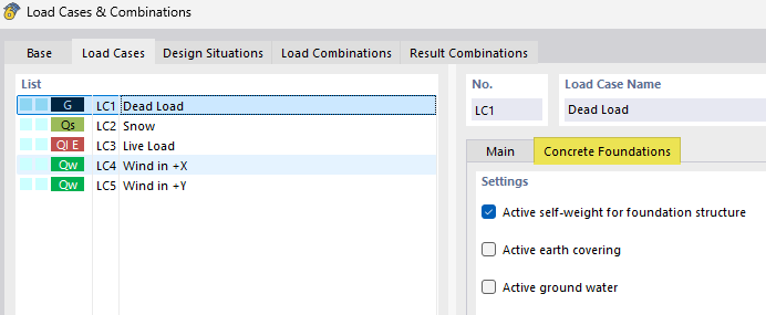
If earth covering and groundwater are activated and their properties have been defined in the Soil Properties dialog box, the corresponding loads are generated automatically. If they are deactivated, you must define them manually as additional foundation loads, if necessary. An explanation of this can be found in the Earth Covering and Groundwater chapters.
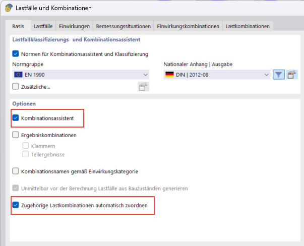
To combine the self-weight in the ultimate limit state also with the partial safety factor of 1.0, select the Favorable permanent actions check box in the 'Options II' section of the Combination Wizard.

Assigned characteristic load combinations
For the geotechnical designs of Ground Failure and Sliding, it is necessary to assign an associated characteristic load combination (SLS) to each ULS load combination. You can do this in the Load Cases and Combinations tab. The SLS combination is required to calculate the load eccentricity and the shear resistance correctly. Without this assignment, the corresponding designs cannot be performed.
When using the load combination wizard, the associated load combinations are assigned automatically.