


For reinforced foundations, it is necessary to determine the design moments for the bending reinforcement of the slab from the soil pressure. In this context, a distinction must be made between two pairs of design moments:
- Design moment pair for the bottom reinforcement of the plate
- Design moment pair for the top reinforcement of the plate
These design moment pairs consist of the design moments for the respective reinforcement in the direction of the main axes of the support coordinate system.
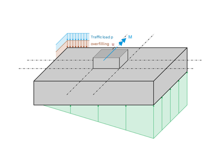
The image shows a foundation subjected to a simple load. A straight-line stress distribution occurs beneath the foundation block. It is necessary to determine the exact stress under the four corner points of the foundation as well as in the center of the foundation and, if necessary, the distribution of a gaping joint. Once the stress distribution below the foundation block is known, the design moments for the bottom plate reinforcement in the x and y directions can be determined.
Design Sections
The design moments are determined based on what are known as “design sections”. The procedure depends on how the column is connected to the foundation plate. The program automatically determines the appropriate design sections for the individual connection types (some foundation types are still in preparation).
Column Without Bucket or Block Foundation

The design sections are drawn along the external sides of the column. This results in the distances Δx and Δy of the respective design sections from the corresponding parallel axes of the support coordinate system as follows:
|
cx |
Column dimension in the x-direction |
|
cy |
Column dimensions in the y-direction |
Bucket Foundation with Smooth Bucket Sides

As in the case of a column without bucket, the design sections are drawn along the external sides of the column.
Bucket Foundation with Rough Bucket Sides

The design sections are drawn through the center of the bucket sides. This results in the following distances:
|
cx |
Column dimension in the x-direction |
|
cy |
Column dimensions in the y-direction |
|
a2 |
Top column allowance |
|
to |
Top bucket wall thickness |
Stepped Foundation

For a stepped foundation, two design sections are distinguished: one for the first step and one for the foundation plate.
The design section of the first step (bottom reinforcement) runs through the edge of the column, but with an inward offset of 0.15 times the column thickness. The distances Δx and Δy of the design sections from the corresponding parallel axes of the support coordinate system are calculated as follows:
The design section of the foundation plate (bottom reinforcement) runs through the edge of the step.
Design Moments
First, the resultant of the compressive stress is determined as the volume of the compressive stress body beyond the design section. Then, the distance between the center of gravity of this compressive stress solid and the design section is determined. The product of the resulting compressive force multiplied by the distance to the design section gives the compressive moment Md.
The compressive moment Md is thus determined from a compressive stress that also includes components of loads that directly act on the soil in their direction of action, and therefore do not cause any bending of the foundation plate. These compressive stress components arise from the self-weight of the foundation plate, the earth covering, and, if applicable, an additional uniformly distributed surface load. These components must be subtracted from the compressive moment. This is done by multiplying the foundation area up to the design section by the distance of the center of gravity and then by the corresponding surface loads. In this way, the component MG of the compressive moment is calculated, which does not cause any bending and for which it is, therefore, necessary to subtract it from Md. The remaining difference then gives the design moment Mbottom.

This way, the design moments for the reinforcement in the x and y directions are determined.
The design moment for the top plate reinforcement is similarly calculated from the difference between the moments due to soil pressure and gravity load.
