


In the Navigator category Verification Results, you can control which verifications, together with their respective utilizations, are displayed graphically on the designed objects. This category contains additional subcategories for the specific verification types:
- Geotechnical design: The specific verification types for the ultimate limit state and the serviceability limit state are available for selection.
- Concrete verification: The reinforced concrete verifications are divided into verifications for the ultimate limit state and for detailing.
Geotechnical verifications
The geotechnical verifications include checking the interaction between the foundation and the subsoil and are carried out for the ultimate limit state and the serviceability limit state. The results are displayed graphically beneath the foundation slab.
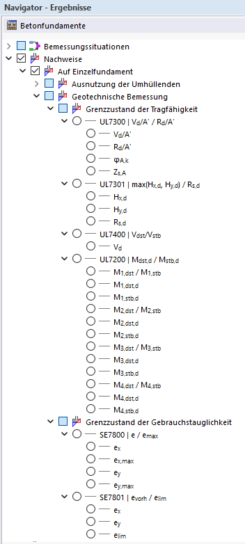
UL7300 | Ultimate limit state (bearing capacity failure)
This verification checks the bearing capacity of the subsoil beneath the foundation. In the Navigator, the following result values can be selected for graphical display:
- Vd/Rd – utilization of the verification
- Vd/A' – design value of the bearing capacity failure action
- Rd/A' – design value of the bearing capacity failure resistance
- φA,k – design value of the effective friction angle beneath the foundation
- Zs,A – slip surface depth
The results are displayed as iso-surfaces beneath the foundation slab and show the distribution of the soil pressures as well as the utilization of the subsoil.

UL7301 | Ultimate limit state (sliding)
This verification checks the safety against sliding of the foundation due to horizontal actions. In the Navigator, the following result values can be selected for graphical display:
- Hx,d – design value of the horizontal force in x-direction
- Hy,d – design value of the horizontal force in y-direction
- Rd – resistance against sliding
The results show the governing horizontal forces and the available resistance against sliding.

UL7400 | Ultimate limit state (uplift)
This verification checks the safety against uplift of the foundation due to buoyancy forces. In the Navigator, the following result values can be selected for graphical display:
- Vd – acting vertical load (resultant)
The results show the equilibrium between buoyancy forces and stabilizing forces.

UL7200 | Ultimate limit state (stability)
This verification checks the stability of the foundation against overturning due to moment loading.
In the Navigator, the following result values can be selected for graphical display:
- Md,stb – stabilizing moment
- Md,dst – destabilizing moment
The verification is performed separately for each foundation edge. From the individual verifications, the governing utilization is determined as the maximum and output. The results allow the assessment of the foundation's stability with regard to overturning.

SE7800 | Serviceability limit state (eccentric loading)
This verification assesses the serviceability of the foundation under eccentric loading. In the Navigator, the following result values can be selected for graphical display:
- ex – eccentricity in x-direction
- ey – eccentricity in y-direction
- emax – maximum eccentricity in x- and y-direction
The results show the position of the resultant within the foundation area and enable the assessment of the load distribution.

SE7801 | Serviceability limit state (foundation rotation)
This verification checks whether the resultant of the load lies within the permissible core area of the foundation and thus no inadmissible rotation or lifting of the foundation slab occurs.
In the Navigator, the following result values can be selected for graphical display:
- ex – eccentricity in x-direction
- ey – eccentricity in y-direction
- elim – limit value of the permissible eccentricity
The evaluation is based on the position of the resultant with respect to the foundation dimensions. If the permissible eccentricity is exceeded, the compressive force leaves the core area, which can cause tensile stresses in the soil joint.

Concrete verifications
The concrete verifications include checking the foundation slab in the ultimate limit state and determining the required reinforcement.
UL2400 | Punching shear resistance
This verification checks the punching shear resistance of the foundation slab in the load introduction area.
The following result values are available for graphical display:
UL2400 – Punching shear resistance according to EN 1992-1-1 (VRd,c)
- VEd,red – reduced acting shear force
- VRd,c – punching shear resistance without punching shear reinforcement
- σz – governing compressive stress beneath the foundation slab
- β – increase factor for considering moments
UL2401 – Punching shear resistance at the column perimeter or perimeter of the load introduction area according to EN 1992-1-1 (VRd,max)
- VEd – acting shear force
- VRd,max – maximum punching shear resistance
The results are displayed in the load introduction area and enable the assessment of the utilization as well as the governing influence quantities of the punching shear verification.

For stepped foundations, two additional verifications for the first foundation step are available (UL2402 and UL2403). Further information on this can be found in the section Durchstanzen .

UL2100 | Plate flexural failure
This verification checks the flexural resistance of the foundation slab in x- and y-direction as well as for the top and bottom reinforcement.
The results are organized by direction (x- and y-direction) and position (top or bottom of the foundation slab) and are evaluated for individual Durchstanzen .

The following result values are available for graphical display:
Static longitudinal reinforcement areas per design strip
- as,stat,1,x,(bottom) to as,stat,4,x,(bottom) – static longitudinal reinforcement areas in x-direction for the bottom reinforcement
- as,stat,1,y,(bottom) to as,stat,4,y,(bottom) – static longitudinal reinforcement areas in y-direction for the bottom reinforcement
- as,stat,1,x,(top) to as,stat,4,x,(top) – static longitudinal reinforcement areas in x-direction for the top reinforcement
- as,stat,1,y,(top) to as,stat,4,y,(top) – static longitudinal reinforcement areas in y-direction for the top reinforcement
Design moments
- Mx,(bottom),d, My,(bottom),d – design moments for the bottom reinforcement
- Mx,(top),d, My,(top),d – design moments for the top reinforcement
Additional result value
- σz – compressive stress beneath the center of the foundation slab
The results enable a differentiated assessment of the bending action as well as the required reinforcement in the individual design strips.
In addition, the compressive stress distribution in the soil joint is displayed graphically with values at corner nodes and beneath the center of the foundation slab.

Display type
The Display type category in the lower Navigator area provides the option of displaying the results as iso-surfaces or isolines. There you can also turn off the graphical display completely.
