


For some standards, the Standard Parameters tab is available in the “Ultimate Configuration” or “Strength Configuration” dialog box. This tab lists all the coefficients that are relevant to the design checks.
The “Design Settings” are tailored to the sections of the respective standard. The following sections describe the parameters for these standards:
EN 1995
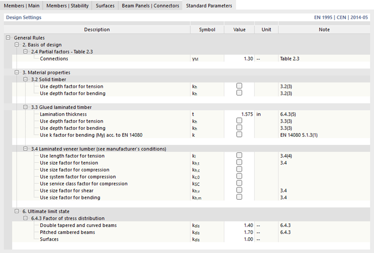
All coefficients relevant to the selected National Annex are listed. The default setting corresponds to the standard requirement or recommendation. The “Note” column specifies the section of the standard to which a parameter refers. Reduction factors are automatically taken into account by default, but increasing factors are not activated. You can manually activate the corresponding coefficients by checking the box if the requirements are fulfilled. In this way, factors that have a favorable effect—such as those for laminated veneer lumber—can be included in the design calculations.
If it is necessary to adjust a coefficient, you can also specify it as a user-defined value. The stress distribution factor kdis plays a particularly important role in duopitch roof beams to consider the effects of transversal tension in curved cross-section distributions.
Use the
 button in the status bar of the dialog box to restore the default values from the National Annex.
NDS
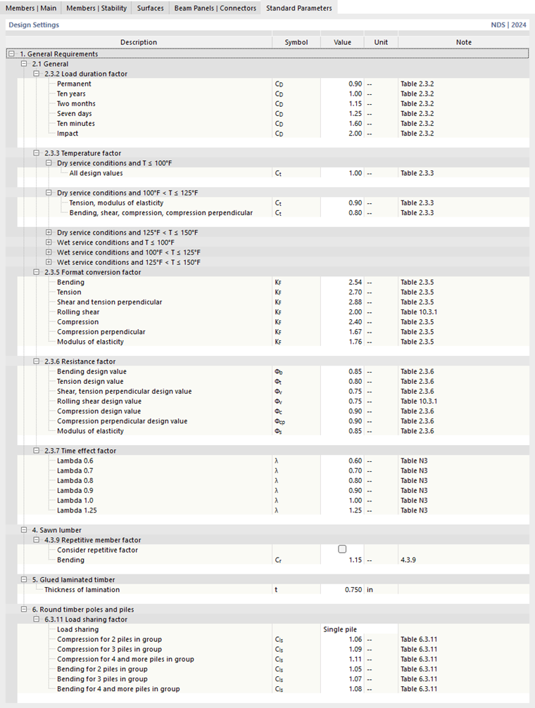
All coefficients relevant to design according to NDS are listed. The default setting corresponds to the standard specification. The “Note” column specifies the section of the standard which a parameter refers to.
Use the
button in the status bar of the dialog box to restore the default values of the standard.
CSA O86
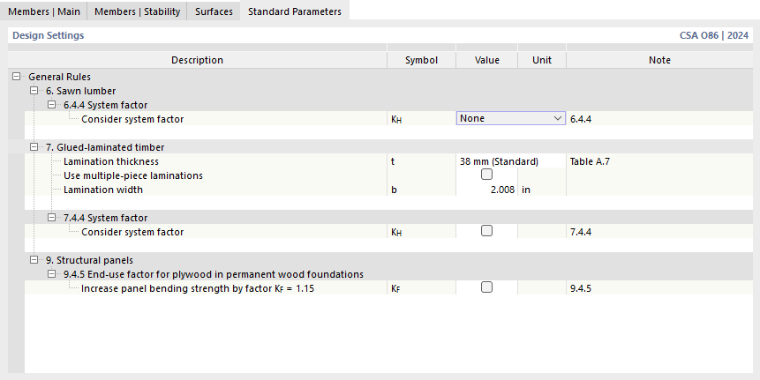
In this tab, you can adjust several parameters that are relevant for design according to CSA.
If structural components made of sawn lumber fulfill the requirements specified in Section 6.4.4, select ‘‘Case 1’’ or ‘‘Case 2’’ from the list to apply the corresponding system factor KH according to Table 6.13.
For structural components made of glued-laminated timber, you can select the thickness of lamination from the list. The thicknesses listed in Table A.7 are included. Check the “Use multiple-piece laminations” option to use the width of the widest part as the effective lamination width b for determining the notched shear strength on the tension side at the support according to Section 7.5.7.5.2. If the option is not checked (single-piece laminations), b corresponds to the full beam width. You can check the width after the calculation in the Design Check Details.
If the glued-laminated timber structural components fulfill the requirements specified in Section 7.4.4, select the “Consider system factor” option. The factor KH is assumed to be KH = 1.10 for all strength properties (with the exception of tensile strength parallel to the grain, shear strength at notches on the compression side, and shear strength at a notch, for which KH = 1.00).
For structural panels made of plywood in permanent wood foundations, you can ‘‘Increase panel bending stiffness by factor KF = 1.5’’ according to Section 9.4.5.