On the Members | Basis tab of the 'Ultimate configuration' or 'Strength configuration' dialog, you can define basic settings for the design of members and member sets.
The 'Design parameters' are organized into several categories, which vary depending on the design standard. The following sections describe the parameters for these standards:
EN 1995

General
The 'Perform stability analysis' check box controls whether stability analyses, such as flexural buckling or lateral-torsional buckling, are performed in addition to the cross-section checks. You should deactivate the check box if you do not want to perform a stability analysis or if you have already taken stability effects into account in the determination of internal forces (for example, by using a second-order analysis with imperfections and/or stiffness reduction).
If the stability analysis is activated, effective lengths must be defined and assigned to the respective members or member sets. If this is not the case, a stability analysis is not possible. An appropriate message is displayed after the calculation in the results table Errors & Warnings. Tension members are exempt from this, as they can only absorb tensile forces and do not require stability analyses.
Design Ratio Limits to Ignore Internal Forces and Stresses
The design standards, which are mostly designed for manual calculations, contain design formulas or interaction conditions that are often only applicable for certain internal force combinations. In the context of structural analysis on a 3D model, however, very small values are usually obtained for internal forces. Although they are insignificant for the load capacity from an engineering point of view, they prevent certain design checks or force the use of less favorable interaction formulas if the design standard is strictly observed. The design ratio limits therefore offer a simple and transparent way to neglect stresses from very small internal forces in the design checks and to circumvent the problems mentioned above.
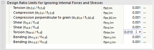
The limit value η describes the ratio of the existing stress to the design value of the strength, which is determined in a simplified manner via the cross-section properties. The limit ratios of the design load capacities are derived from the standard specifications and are preset with very small values to enable a simplified design. You should therefore only use high limit values for testing purposes.
If an internal force is below the limit value condition, the design is performed without a warning that the internal force is neglected. In the design check details, however, you can check which internal forces were neglected due to the limit values and not considered in the design by means of the 'Negligible' note for the design internal forces. If all internal forces are negligible at a point, only the check of the negligible internal forces is specified as the design check.

Curved Members and Tapered Beams with Curved Bottom Edge
With the check boxes, you can control whether the design of stresses perpendicular to the grain direction should also be performed for non-uniform section distributions. This perpendicular-to-grain tension check often proves to be a weak point for curved members.
'Tapered beams with curved bottom edge' represent members with a section distribution of the 'Saddle' type. For these members, you can also specify whether the perpendicular-to-grain tension check should be performed.
Grain Cut Angle Limitation
For members with linear or tapered section distribution, the wood fibers are cut through at the beveled edge. According to [1] 6.4.2, the influence of the grain cut angle α on the stresses at the cut edge must be taken into account. According to the German National Annex, this angle must not be too large and may be a maximum of 24°. You can adjust the default limit value if necessary to enable further design.
System Strength According to 6.6
If the continuous load distribution system with similar components at equal spacings (for example, floor beams all next to each other) is able to transfer loads from one member to adjacent members, the strength of the components may be increased by the factor ksys according to [1] 6.6. If this is the case, tick the check box.
Increase of Shear Crack Factor
This category is available for design according to the German National Annex. It concerns the influence of cracks on the shear capacity check of members subjected to bending. If you activate the option, the factor kcr for the shear design of softwood cross-sections at a distance of more than 1.5 m from the member ends is increased by 30%. It is assumed that the cracks there only have small dimensions.
NDS

General
The 'Perform stability analysis' check box controls whether stability analyses, such as flexural buckling or lateral-torsional buckling, are performed in addition to the cross-section checks. You should deactivate the check box if you do not want to perform a stability analysis or if you have already taken stability effects into account in the determination of internal forces.
For more information, see the General section in the description for the EN 1995 standard.
Design Ratio Limits to Ignore Internal Forces and Stresses
The design equations of the design standards are often only applicable for certain internal force combinations. In general, the structural analysis on a 3D model also leads to very small values for "secondary" internal forces, which are insignificant for the load capacity from an engineering point of view, but prevent certain design checks if the standard is strictly observed. The design ratio limits make it possible to neglect certain internal forces in the design check and thus to circumvent the problems mentioned above. The limit value η describes the ratio of the existing stress to the design value of the strength.

For more information, see the Design Ratio Limits section in the description for the EN 1995 standard.
Torsion Calculation
With the check boxes, you can control how torsion is taken into account in the design checks:
- Check torsion limit only: Further design is permissible if the shear stress caused by torsion does not exceed the design value of the strength according to [2] Chapter 3.4. If it exceeds the limit value, design is not possible.
- According to Timber Construction Manual: The torsional stresses are designed according to the specifications in [3] Chapter 4.6. In the Design Ratio Limits section, you can specify from which limit ratio η torsional stresses are generally relevant for design.
- Ignore: The shear stresses due to torsion are checked in the design but have no influence on the design. If the design value of the strength is exceeded, the program only issues an informative note.
Positive or Negative Bending About y-Axis
According to [2] Table 5A and Table 5C, specific design values apply for positive bending (bottom side of the beam under tensile stress) and negative bending (top side of the beam under tensile stress) for glulam components subjected to bending about the y/x-axis. Specify whether the bottom side of the members to be designed is in the positive direction of the local z/y-axis or in the opposite direction.
In the other categories, you can make further design-relevant settings. The description is in progress.
CSA O86

General
The 'Perform stability analysis' check box controls whether stability analyses, such as flexural buckling or lateral-torsional buckling, are performed in addition to the cross-section checks. You should deactivate the check box if you do not want to perform a stability analysis or if you have already taken stability effects into account in the determination of internal forces.
For more information, see the General section in the description for the EN 1995 standard.
Design Ratio Limits to Ignore Internal Forces and Stresses
The design equations of the design standards are often only applicable for certain internal force combinations. In general, the structural analysis on a 3D model also leads to very small values for "secondary" internal forces, which are insignificant for the load capacity from an engineering point of view, but prevent certain design checks if the standard is strictly observed. The design ratio limits make it possible to neglect certain internal forces in the design check and thus to circumvent the problems mentioned above. The limit value η describes the ratio of the existing internal force to the design value of the cross-section resistance.
For more information, see the Design Ratio Limits section in the description for the EN 1995 standard.
Positive or Negative Bending About y-Axis
According to [2] Table 5A and Table 5C, specific design values apply for positive bending (bottom side of the beam under tensile stress) and negative bending (top side of the beam under tensile stress) for glulam components subjected to bending about the y/x-axis. Specify whether the bottom side of the members to be designed is in the positive direction of the local z/y-axis or in the opposite direction.