In the result tables for the “Timber Design” category, you can view the design check details using one of the following methods:
- The
 button on the table toolbar
- Double-click a result row
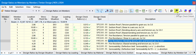
The “Design Check Details” dialog box appears. It displays the design equations along with the intermediate results of the design check that apply to “the result selected in the table.”
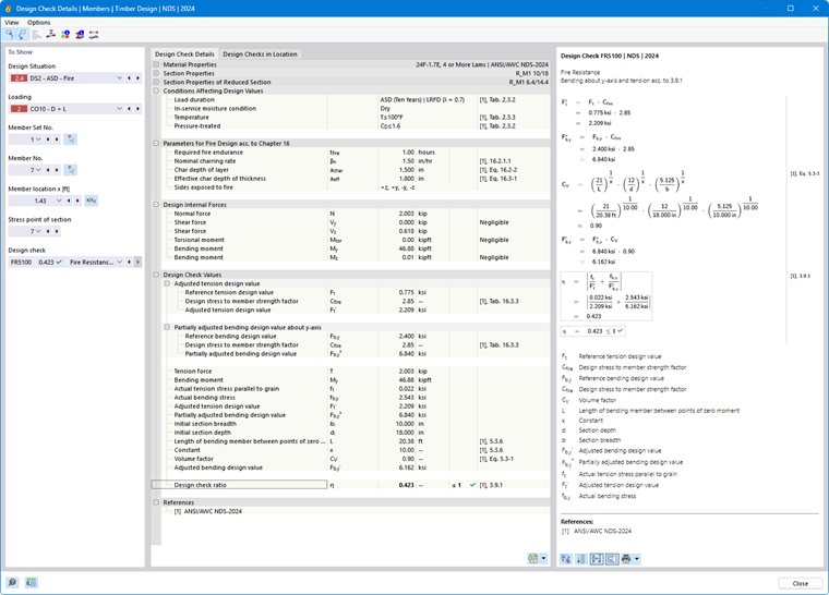
In the central area, you’ll see the detailed results; in the right column, the design equations.
To Show
The section on the left shows the parameters of the table row that is selected when the dialog box is opened. This allows you to control the design situation, the governing objects, and the design criterion.
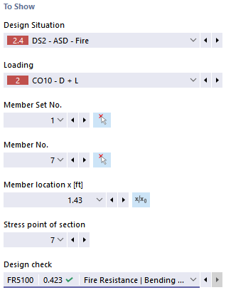
If you want to review the details for a different scenario, you can adjust the parameters—design situation, load, object, x-location or mesh node, stress point or layer, and design—at any time using the drop-down lists. Selection options are available for all calculated result types. For example, if only members were analyzed, no options for member sets or surfaces will be displayed. Similarly, you cannot switch to member design in the design check details for surfaces. In this case, select the corresponding result table in the program without closing the “Design Check Details” dialog box.
If you want to review the results for another object, you can graphically select the member or surface in the work window using the
 button.
For the results of a member set, the list of members only contains the member numbers belonging to that set. Similarly, for the results of a surface set, the list only contains the associated surfaces. If you activate the
 button for a member set, “Member location x” refers to the start of the member set. If it is inactive, the x-location refers to the start of the selected member. Members designed without a member set are available in the list if you select the --' entry for “Member Set No.”
For stress points, a selection option is only available for design checks that are related to a stress point (for example, stress analysis) For other design checks, such as serviceability, the “--” entry is displayed.
Design Check Details
In the central area in the Design Check Details tab, the key input parameters, intermediate values, and design results are listed in a tree structure (see the image Design Check Details for Timber Design). This allows you to follow the design checks step by step.
You can also check the intermediate values in the design check formulas on the right. If you click on a row in the “Design Check Values” category, the corresponding design check formula is highlighted with a border.
The “Design Internal Forces” category lists the internal forces used for the design at this location. If an internal force is marked as “Negligible”, it is below a limit value (see the chapter Members | Main). It is not taken into account in the further design.
Design Checks in Location
The Design Checks in Location tab lists all design checks performed at location x or at the mesh node. Here, you can quickly review the design ratios for various types of design checks.
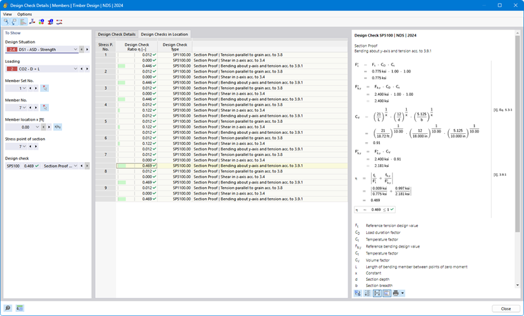
If you click on a row, the corresponding design check formula is displayed on the right. Double-clicking a row takes you to the “Design Check Details” tab, where you can review the intermediate values and results of that design check.
Some design checks—such as stress analyses—are performed at every stress point. Other design checks, such as serviceability limit state design checks, however, do not require a distinction between stress points.
Design Check Formulas
The right section lists the key formulas for determining the intermediate values as well as the final calculation of the design criterion (see the image Design Check Details for Timber Design). When you click on a formula, the corresponding row in the “Design Check Values” category of the design check details is selected. Use the
 button at the bottom to switch between symbolic notation and numerical values, and use the
 button to display a condensed version of the design equation.
You can also use the design check formulas for documentation purposes. The list button
 offers various printing options (see the image Design Check Details).
The
 button allows you to switch between the formulas and the model view. You can thus quickly locate the design location in the model.
Menus “View” and “Options”
In the “Design Check Details” dialog box, you can use the menu functions to open additional dialog boxes for evaluating results or to control the view. Alternatively, you can use the corresponding buttons. They are assigned the following functions:
| Button | Feature |
|---|---|

|
Synchronize design check details with the selected objects in the table |
| Synchronize the result table with the selection in design check details | |

|
Show or hide the colored reference scale in the Design Checks in Location tab |

|
Open the Result Diagrams in Section window |

|
Open the Result Diagrams in Surface Point window |

|
Open a window with information on the material properties of the steel |

|
Open a window with information on the properties of the cross-section |

|
Open the Charring Depth-Time Diagram window |

|
Open the Result Diagrams dialog box |