


The result tables of the category Utilizations by Beam Panel | Connector contain the result data for the designs of the connecting elements of beam panels with the respective utilizations.
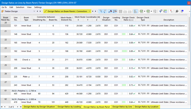
The results are sorted in the tabs according to the following criteria:
- Loads (design situations, load combinations)
- Objects (beam panels, lines, line locations x)
Beam Panel Surface No.
A surface is assigned to each beam panel. The number of this surface is specified here.
Line No.
The number of the line that was generated for the connection of the sheathing and the beam or rib and where the respective utilization occurs is specified.
Beam Type
The position of the member is described here:
- Horizontal member at the top edge (-y) or bottom edge (+y) of the slab (see Beam Panel | Beams)
- Vertical member at the left edge (-x) or right edge (+x) of the slab (see Beam Panel | Beams)
- Internal rib: stud within the slab
Connector Between Sheating / Beam
The numbers of the generated sheathing surfaces and beams or ribs that are connected to each other by clamps or nails are specified in the two columns.
You can activate the numbers of the generated objects in the Navigator - Display with the option Model → Base Objects → Surfaces → Beam Panels for the display. Alternatively, use the
 button in the toolbar.
Design Situation
This column specifies the numbers of the design situations for which the individual utilizations exist.
Loading
The numbers of the load or result combinations that are governing for the respective designs are specified.
Design Criterion
In this column, the design conditions according to the Standard are specified. The degree of the respective utilization is expressed by the length of the colored bar.
Design Check Type
Each design is identified by an ID with a number. For example, the designs of the ultimate limit state according to Eurocode carry the ID 'UL', the designs of the serviceability limit state carry the ID 'SE'. The design check type is explained in the Description column.
Design Formula
You can activate this column in the Result Table Manager. It specifies the equations of the standard according to which the designs are performed.
Description
Each design is explained by a short description with reference to the chapter in the standard.
You can display the Design Check Details for a specific utilization via the
 button or by double-clicking the line.
Filtering Results
The chapter Utilizations by Member describes how to filter the results by limit state and by utilization.