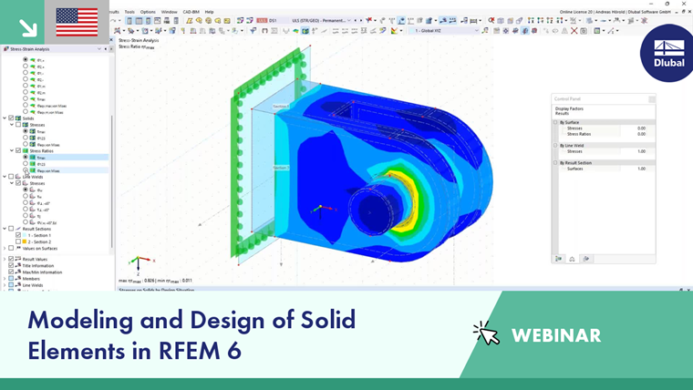
Solids are used to describe the geometry of spatially extended objects. When generating the FE mesh, 3D elements are created on solids. Solids also allow you to model orthotropic and contact properties or perform analyses for gas models.

Generally, the 'boundary surfaces' of the solid should be defined with the Without Thickness stiffness type (see the Surfaces chapter). However, if a model representing the contact between two surfaces does not have another solid adjacent, both contact areas must be assigned a stiffness.
Base
The Base tab manages the fundamental parameters of the solid.
Solid Type
The solid type controls how internal forces are absorbed or which properties apply to the solid. Various types are available for selection in the list.
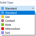
Standard
The Standard model represents a 3D object with the solid-specific properties of a homogeneous and isotropic material. The boundary surfaces should therefore be defined with the 'Without Thickness' stiffness type .
If the solid has orthotropic properties, the stiffnesses are also derived from the material values. You can define the elastic stiffnesses of the three-dimensional material model in the Orthotropic - Linearly Elastic (Solids) tab of the material dialog box.
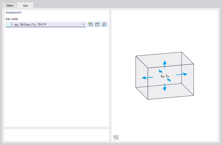
Gas
This type allows you to model solids that have the properties of an ideal gas, such as air cushions, pressure vessels, or insulating glass. You can assign or redefine the pressure and temperature properties of the gas in the 'Gas' tab (see the Gas Solids chapter).
Contact
This solid type is suitable for modeling the contact between two surfaces. You can define the contact properties in the 'Contact Solid' tab.
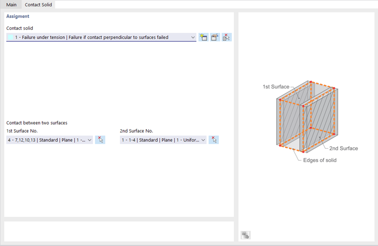
Select the contact solid type from the list or create a new contact with the appropriate properties (see the Contact Solids chapter).
If the geometry permits, two opposite contact surfaces are preset. You can change the '1st surface' via the list or determine it graphically using the
![]() button. RFEM automatically sets the solid surface that is parallel to the first surface as the '2nd surface'.
button. RFEM automatically sets the solid surface that is parallel to the first surface as the '2nd surface'.
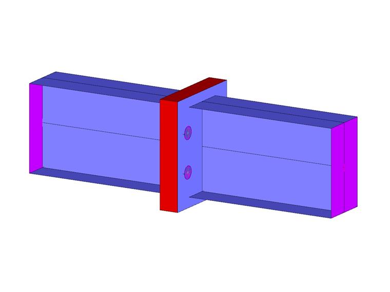
Hole
With this solid type, you can create recesses or openings for bolts and the like. This type is also suitable for modeling a construction pit for the special solution add-on Geotechnical Analysis.
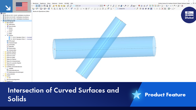
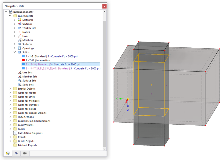
Intersection
If two solids intersect, you can create the intersection by assigning the 'Intersection' type to one of these solids. After a query, RFEM creates the intersecting lines and the intersection. In the Navigator, the components of the (other) 'Standard' solid are added as generated objects.
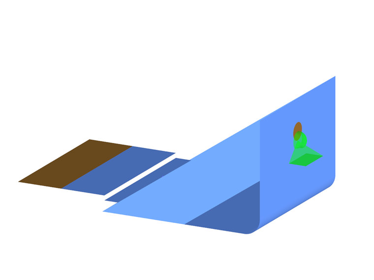
Soil
This solid type is used for the special solution add-on Geotechnical Analysis.
Material
In the list of existing materials, select the appropriate type or define a new material (see the Materials chapter).
Mesh Refinement
The mesh size of the FE mesh can be adjusted to the geometry of the solid (see the Solid Mesh Refinements chapter). It is therefore independent of the general mesh settings.
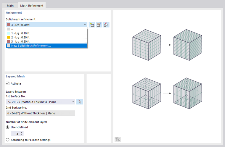
In the 'Mesh Refinement' tab, you can select or redefine the solid mesh refinement. Alternatively, in the 'Layered Mesh' section, you have the option to arrange an FE division of the solid by layers that are to be generated between two parallel opposing surfaces. This function is briefly introduced in a Video.
Specific Direction
Every solid has a local coordinate system. By default, it is oriented parallel to the global axes. However, the coordinate system can also be defined by the user.

The list in the 'Direction Type' section provides various options for adjusting the axis orientation of the solid:
- Rotated via 3 angles: Rotation of the xyz-axes by the angles αX', αY', and αZ' with respect to the global axes
- Directed to node: Orientation of the '1st axis' (x-axis) and the '2nd axis' (y-axis) each towards a node
- Parallel to two nodes: Orientation of the '1st axis' (selectable) parallel to two nodes and the '2nd axis' (selectable) towards a node
- Parallel to CS of line: Orientation of the x-axis parallel to the x-axis of a line
- Parallel to CS of member: Orientation of the x-axis parallel to the x-axis of a member
- Parallel to CS of boundary surface: Orientation of the x-axis parallel to the x-axis of a boundary surface
You can determine the reference objects graphically using the
![]() button.
button.
The axis system is also used for the output of results.
Stiffness Matrix
This function is still in preparation. The check box is intended to allow the manual definition of the solid's stiffness matrix in a tab.
Integrated Objects
If an object lies within the solid but was not used for the solid definition, it is not automatically part of the solid. It must be integrated manually so that a connection with the solid exists.

Enter the numbers of the integrated nodes, lines, and surfaces, or use the
![]() button to determine the objects graphically. If you add an object in the 'Integrated Objects for Independent Mesh' section, the FE mesh settings apply to the solid. If you want to apply specific specifications for the FE mesh for the object (for example, for a bored pile in the soil massif), enter the number in the 'Integrated Objects for Independent Mesh' section. This means that the object's own specifications apply – regardless of the global setting for the 'Prefer independent mesh' option in the Mesh Settings dialog box.
button to determine the objects graphically. If you add an object in the 'Integrated Objects for Independent Mesh' section, the FE mesh settings apply to the solid. If you want to apply specific specifications for the FE mesh for the object (for example, for a bored pile in the soil massif), enter the number in the 'Integrated Objects for Independent Mesh' section. This means that the object's own specifications apply – regardless of the global setting for the 'Prefer independent mesh' option in the Mesh Settings dialog box.
Deactivate for Calculation
The check box provides the option to exclude the solid from the calculation, for example, to simulate construction stages or investigate a modeling variant. In this case, the stiffness, properties, and loads of the solid are not applied.
Information | Analytical
This section provides an overview of important properties of the solid, such as surface area, volume, and mass, as well as the location of the centroid.