


Solutions for Finite Element Analysis (FEA)


Recommended Products for Finite Element Analysis (FEA)
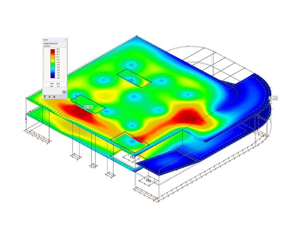
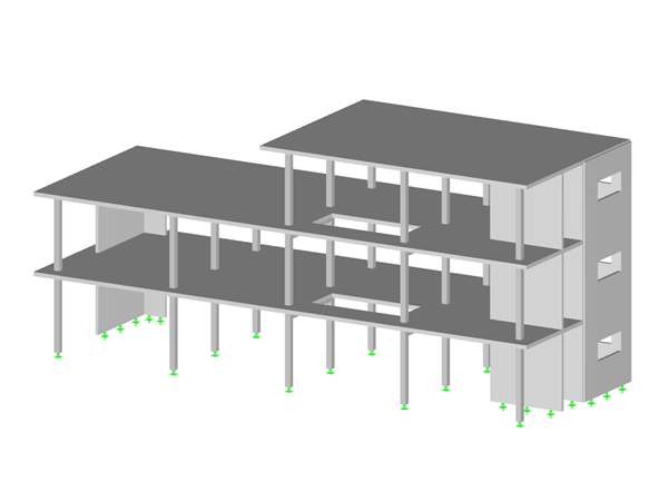
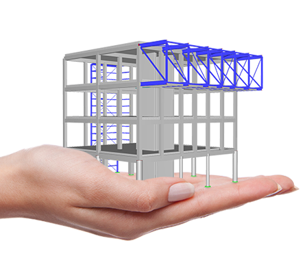
Construction Stages
The Construction Stages Analysis (CSA) add-on allows for considering the construction process of structures (member, surface, and solid structures) in RFEM.
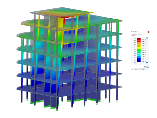
Time-Dependent Analysis (TDA)

The Time-Dependent Analysis (TDA) add-on allows you to consider the time-dependent material behavior of members and surfaces. The long-term effects, such as creep, shrinkage, and aging, can influence the distribution of internal forces, depending on the structure.

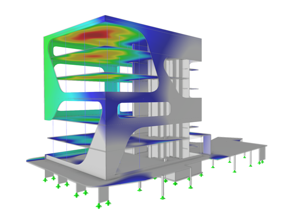
Geotechnical Analysis
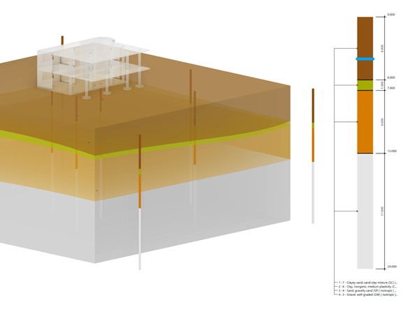
In RFEM, the Geotechnical Analysis add-on uses the properties from soil samples to determine a soil body to be analyzed.
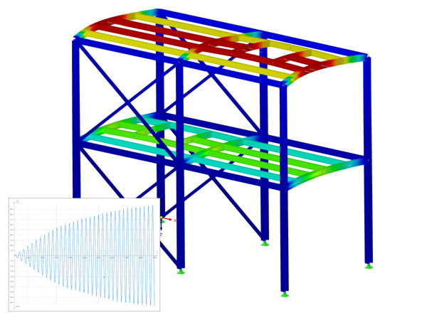
Response Spectrum Analysis
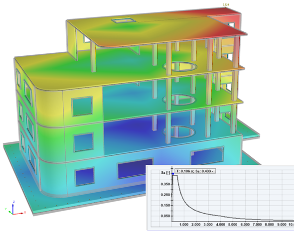
The Response Spectrum Analysis add-on performs seismic analysis using multi-modal response spectrum analysis. The spectra required for this can be created in compliance with the standards or can be user-defined. The equivalent static forces are generated from them. The add-on includes an extensive library of accelerograms from seismic zones that can be used to generate the response spectra.

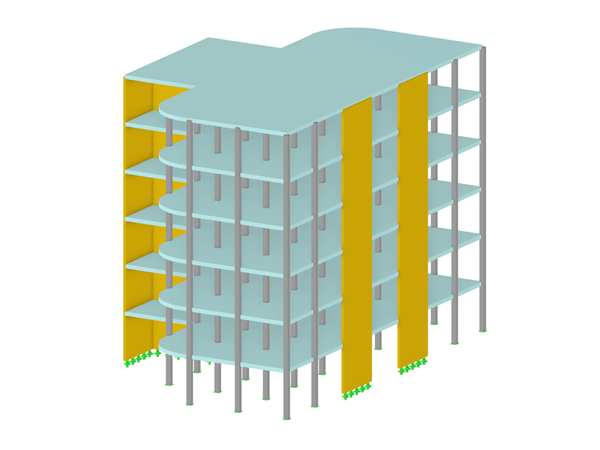
Definition of Multilayer Surfaces Such as Cross-Laminated Timber (CLT)

The Multilayer Surfaces add-on allows you to define multilayer surface structures. The calculation can be carried out with or without the shear coupling.


Whether you require nonlinear time history analysis for machine-induced vibrations, cable and FEA shell analysis, form-finding, BIM and BIM Connector, or RFEM 6 and RSTAB 9, if you want to succeed, you need to use Dlubal Software!

Danzl
Raiffeisenplatz 5/T8, Feldkirch
Germany

.png?mw=600&hash=49b6a289915d28aa461360f7308b092631b1446e)
Support and Learning
We provide professional support and many services in order to help you with finding a quick and efficient solution for your projects.


.png?mw=200&hash=ceabdac71454991b172d1a40faa3844b9a756ff1)

World's Longest Suspension Footbridge in Dolní Morava, Czech Republic
In May 2022, the new Sky Bridge footbridge opened in the Dolní Morava area (Czech Republic); it is the longest footbridge in the world, with a length of 721 m (2,365.5 ft). The design and construction of the footbridge were carried out by TAROS NOVA a.s., and the calculation was performed in RFEM 5.
-
Project Location
Mountain Resort Dolní Morava
-
Software
RFEM 5.xx
.png?mw=80&hash=24e105a767cf2e175614b729c2d2fa1673e4e81b)
Technical Support | Sales Team