What is axial compression?
A section of a structural element is stressed by axial compression when the forces acting on one side of the section are reduced at the section's center of gravity to a single force N. Thus, the normal force N is perpendicular to the cross-section and directed towards the cross-section. In contrast to combined bending, this stress is never encountered in practice, because a real column is always subjected to either the asymmetry of the loading or to imperfections in the column construction, as can be seen in this technical article:
Slenderness Criterion for Isolated Elements
It is assumed that the second-order effects (imperfections, asymmetry, and so on) can be neglected if the element is only stressed by a normal compression force NEd and if the slenderness criterion is fulfilled.
Slenderness Criterion
λ < λlim
λ … Slenderness coefficient
λlim … Limiting slenderness
Slenderness and Effective Length According to EN 1992-1-1
|
λ |
Coefficient d'élancement |
|
l0 |
Longueur efficace = kcr ⋅ l |
|
i |
Rayon de giration de la section de béton non fissurée |
|
kcr |
Facteur de longueur efficace = 0,5 ⋅ √[(1 + k1 / (0,45 + k1)) ⋅ (1 + k2 / (0,45 + k2))] selon 5.8.3.2(3) formule (5.15) |
|
l |
Longueur libre |
|
k1, k2 |
Coefficients de souplesse aux deux extrémités de l'élément |
Limiting Slenderness According to EN 1992-1-1
Limiting slenderness
λlim = (20 ⋅ A ⋅ B ⋅ C) / √n according to 5.8.3.1(1) Formula (5.13N)
A = 1 / (1 + 0.2 φef) = 0.7 if φef is unknown
B = √(1 + 2 ⋅ ω) = 1.1 if ω is unknown
C = 1.7 - rm = 0.7 if rm is unknown
n = NEd/(Ac ⋅ fcd ) … Relative normal force
φef … Effective creep coefficient
ω … Mechanical reinforcement ratio
rm … Moment ratio
NEd … Design value of acting axial force
Ac … Total area of pure concrete section
fcd … Design value of the compressive strength of concrete
Compressive Stress in Steel
The concrete shrinkage under axial compression is limited to εc2 in the case of the σ-ε parabola-rectangle diagram. By static friction of concrete and steel, the shortening is identical for the reinforcement, and we can deduce its stress.
|
σs |
Contrainte dans l'armature |
|
fyd |
Limite d'élasticité de calcul de l'acier de béton armé = fyk / γs |
|
εc2 |
Déformation relative en compression pour la contrainte maximale |
|
Es |
Module d'élasticité |
|
fyk |
Limite d'élasticité caractéristique |
|
γs |
Coefficient partiel de l'acier |
|
εud |
Déformation limite de calcul = fyd / Es |
Compressive Stress in Concrete
Stress in concrete
fcd = αcc ⋅ fck / γc
αcc … Factor considering long-term actions on compressive strength
fck … Characteristic compressive strength of concrete
γc … Partial safety coefficient relating to concrete
Dimensions of Concrete Cross-Section
The force that can be balanced by the concrete cross-section corresponds to its maximum load-bearing capacity for compression, which depends directly on its section and its design resistance.
Equilibrium force of concrete
Fc = Ac ⋅ fcd
The reinforcement will balance the rest of the axial compressive load.
Equilibrium force of reinforcement
Fs = NEd - Fc
From these two equilibrium equations, it is possible to deduce the concrete cross-section to be designed, then that of the reinforcing steel.
Area of concrete cross-section
Ac ≥ NEd / (fcd + As / Ac ⋅ σs)
As = Fs/σs … Cross-sectional area of the reinforcement
Application of Theory Using RF-CONCRETE Members
In this article, we will analyze the results obtained automatically for the reinforcement calculation. As the objective is also to determine the concrete cross-section to be designed, the RFEM 5 basis model will have a specified width and an unknown height equal to or greater than the width.
We will consider the following parameters:
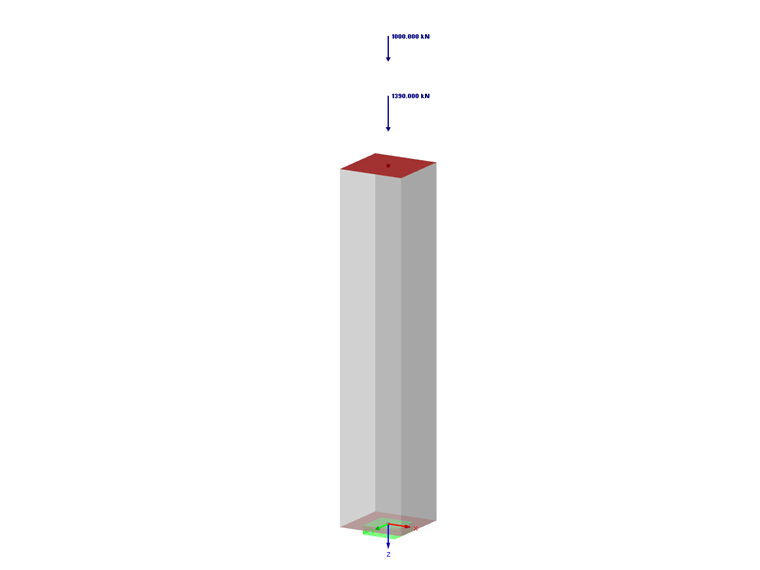
- Permanent loads: Ng = 1,390 kN
- Variable loads: Nq = 1,000 kN
- Column length: l = 2.1 m
- Rectangular cross-section to be determined: width b = 40 cm / unknown height ≥ 40 cm
- The column's self-weight can be ignored.
- Column not integrated into bracing.
- Concrete strength class: C25/30
- Steel: S 500 A for inclined graph
- Diameter of longitudinal reinforcement: ϕ = 20 mm
- Diameter of transverse reinforcement: ϕt = 8 mm
- Concrete cover: 3 cm
Material Properties
Design value of the compressive strength of concrete
fcd = 1 ⋅ 25 / 1.5 = 16.7 MPa
Relative compression strain for maximum stress
εc2= 2‰
Design yield strength of reinforcing steel
fyd = 500 / 1.15 = 435 MPa
Limit strain in reinforcement
εud = fyd / Es = 435 / (2 ⋅ 105) = 2.17‰
Stress in reinforcement
σs = 2 ⋅ 105 ⋅ 0.002 = 400 MPa as εc2 < εud
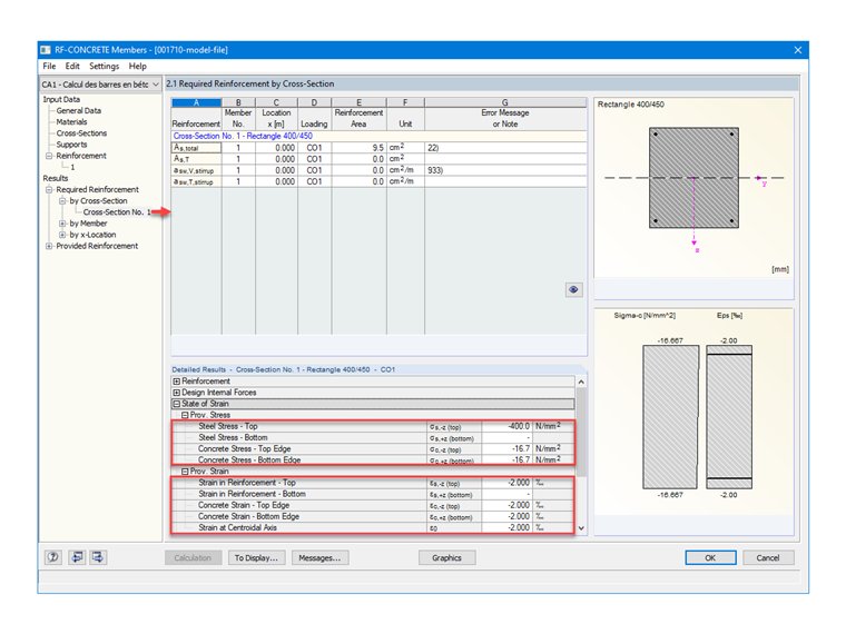
In order to verify the material settings in RF‑CONCRETE Columns, Image 02 shows the expected stresses and strains for the concrete and the required reinforcement.
´État Ultimate Limit State
Ultimate limit state design loads
NEd = 1.35 ⋅ Ng + 1.5 ⋅ Nq
NEd = 1.35 ⋅ 1390 + 1.5 ⋅ 1000 = 3.38 MN
Second-Order Effects Not Taken into Account in ULS
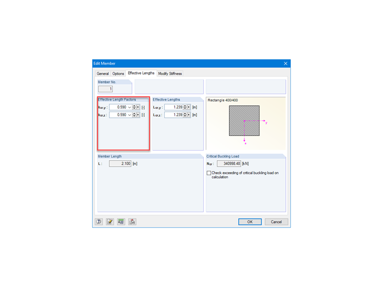
In order to apply the load at the head of the column correctly, we have modeled a member that is restrained only at the base and is free at its head. However, we want to consider the column being fixed at the head to some beams by assuming that the column is less stiff than the beams. We can then consider that the member is fixed at both ends. Thus, in theory, the flexibility coefficients should be zero for a perfect restraint. However, the perfect restraint does not exist in practice. Therefore, the minimum value to be considered for the flexibility coefficients is: k1 ou k2 = 0.1.
Effective length factor
kcr = 0.5 ⋅ (1 + 0.1 / (0.45 + 0.1)) = 0.59
Image 04 shows the possibility of setting the effective length factor for a member type element in RFEM.
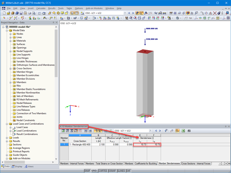
Since the height of the cross-section has to be determined, it is assumed that h > b, and thus, that the radius of gyration of a rectangular cross-section is more governing for the small width.
Radius of governing inertia in plane parallel to width b = 40 cm
iz = b / √12
Slenderness
λz = (0.59 ⋅ 2.1 ⋅ √12) / 0.40 = 10.73 m
Image 05 shows the slenderness values determined for the member after calculation in Table 4.10 of RFEM.
To verify our slenderness, we manually determine the limiting slenderness by assuming h = b.
Limiting slenderness
n = 3.38 / (0.40² ⋅ 16.7) = 1.26
λlim = 20 ⋅ 0.7 ⋅ 1.1 ⋅ 0.7 / √1.26 = 9.6 m
λz > λlim → The condition is not fulfilled.
However, we are still going to calculate in centric compression because, the deviation being small, we note later that with the determination of the real height of the section, the condition will be respected.
Real Height to Be Calculated
In order to determine the real height h of the cross-section, the following hypothesis can be adopted for the reinforcement ratio to be considered: As/Ac = 1%. We can then deduce the real cross-section to be designed and its height as a function of the stress in the reinforcement and the width of the cross-section b.
Area of concrete cross-section
Ac ≥ 3.38 / (16.7 + 400 / 100) = 0.163 m²
Cross-Section Depth
Ac = b ⋅ h → h ≥ 0.163 / 0.4 = 0.41 m
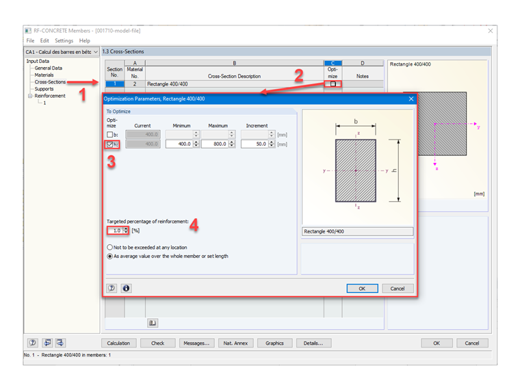
The assumption h > b made for the slenderness calculation is correct, and we can retain a section height by choosing a multiple of 5 cm; that is to say, h = 45 cm.
Image 06 shows the steps to automatically determine the height of the rectangular cross-section in RF‑CONCRETE Members, using the "Optimize" function.
Load-Bearing Cross-Section
Equilibrium force of concrete
Fc = 0.40 ⋅ 0.45 ⋅ 16.7 = 3 MN
Equilibrium force of reinforcement
Fs= 3.376 - 3 = 0.38 MN
We deduce the corresponding reinforcement area:
Reinforcement area
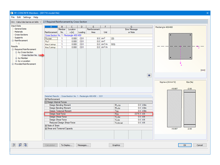
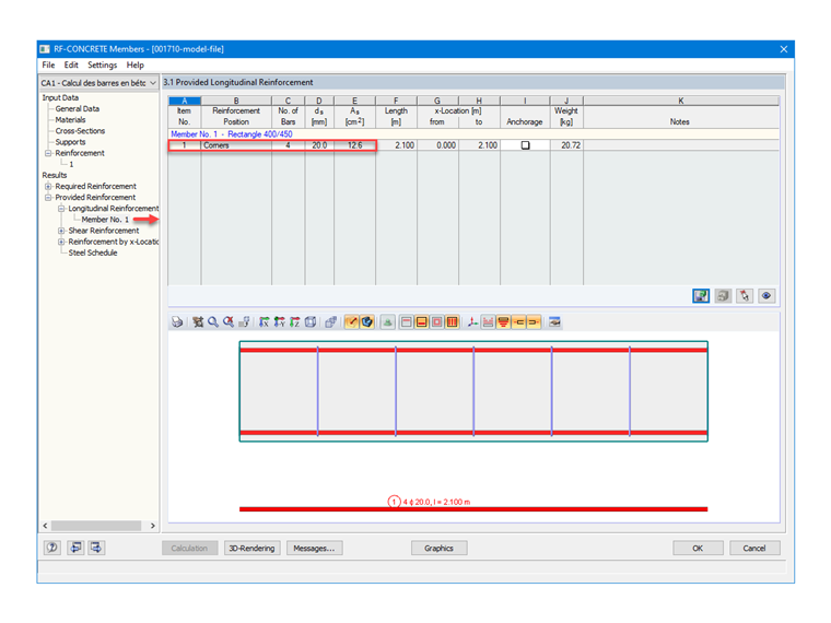
As = 0.38 / 400 ⋅ 104 = 9.5 cm²
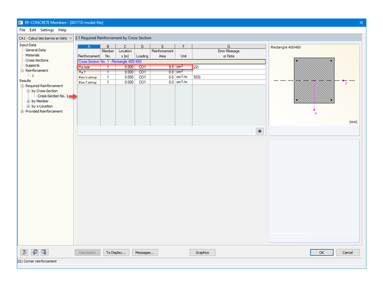
Having set up steels with a diameter of 20 mm in RF‑CONCRETE Members, the reinforcements provided and determined automatically by the module are 4 members, with a distribution in the corners, as requested; that is, 1 HA 20 per corner. Therefore, the result of the cross-sectional area and the following:
As = 4 ⋅ 3.142 = 12.57 cm²
Mechanical reinforcement ratio
ω = (As ⋅ fyd) / (Ac ⋅ fcd) = 12.57 ⋅ 435 / (40 ⋅ 45 ⋅ 16.7) = 0.182
Final check of limiting slenderness as h > b
n = 3.38 / (0.40 ⋅ 0.45 ⋅ 16.7) = 1.125
B = √(1 + 2 ⋅ ω) = 1.17
λlim = 20 ⋅ 0.7 ⋅ 1.17 ⋅ 0.7 / √1.125 = 10.81 m
λz < λlim → The slenderness criterion is fulfilled.
Application in Other Add-on Modules
The RF‑CONCRETE Columns add-on module also allows for determining the reinforcement of a structural element subjected to axial compression. A technical article detailing the differences between RF-CONCRETE Members and RF-CONCRETE Columns can be found here: