


Cross-stiffeners for members can be considered when verifying the shear capacity of web plates in order to limit the buckling fields. Additional verifications, for example, for concentrated load introduction into the stiffener, are not performed.

Assigned to Member / Member Set
Cross-stiffeners for members are organized as Types for Members. Assigning cross-stiffeners to one or more members can thus be carried out via the member's edit dialog, selection in the cross-stiffener dialog, or through the input table (see chapter Steel Design).
Cross-stiffeners can also be assigned to a member set. The position of a stiffener type then refers to the length of the entire member set.
Type and Location of the Stiffener
In the table, you define the stiffeners present on the member with their x-positions. You can toggle between absolute and relative input of the distance using the button
![]() , and sort the list by x-locations with the button
, and sort the list by x-locations with the button
![]() .
.
Various stiffener types are available for selection in the list.
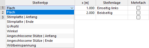
Types like flat stiffeners or angles require specifying the 'Stiffener Location': left, right, or on both sides. The left side is considered the side lying in the negative y-direction of the member.
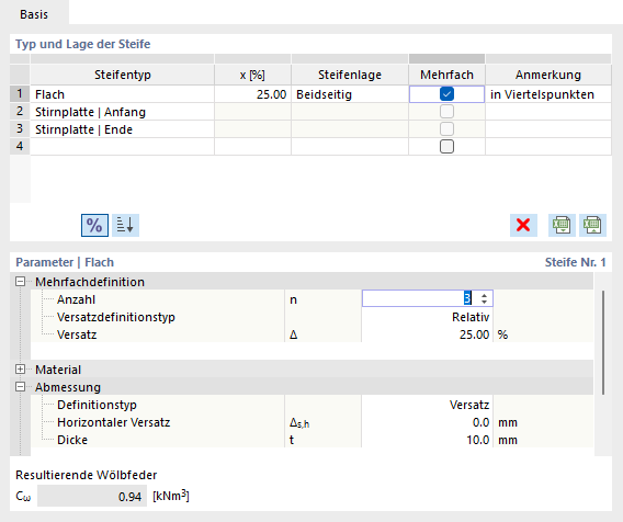
If the member has multiple stiffeners of the same type, check the 'Multiple' checkbox. In the 'Parameters' section, you can then specify the number and offset (distance) of the stiffeners.
Parameters
In the lower dialog section, define the main properties of the stiffener. The parameters refer to the entry selected in the table Type and Location of the Stiffener. Generally, specifications for the material and dimensions of the stiffener are required.

With the definition type 'Offset', you can define the width of the stiffener with reference to the cross-sectional contour: A horizontal offset Δs,h = 0 aligns the stiffener flush between the outer edges. If you switch to the 'Size' option in the list, you can directly specify the width b.
To ensure the stiffener is considered in steel design, the checkbox Consider Stiffener in the 'Design Add-Ons' category needs to be activated. This option is not available for all stiffener types depending on the design standard. A classification regarding the deformability of the stiffener might be necessary.
Resulting Warping Spring
When the add-on Warping Torsion (7 Degrees of Freedom) is activated, cross-stiffeners for members are used to define warping springs in the calculation of members with seven degrees of freedom. For more information, refer to chapter Cross-Stiffeners for Members of the add-on manual.
When using cross-stiffeners for steel design, the displayed warping spring stiffness serves merely as information. There is no automatic transfer for entering the nodal supports in the dialogs of Buckling Lengths or Boundary Conditions.