


Member transverse stiffeners can be taken into account in the shear resistance design of web plates in order to limit the buckling panels. Further design checks, for example, for concentrated load introduction into a stiffener, are not performed.

Assignment to Member / Member Set
Member transverse stiffeners are organized as a [[#/de/downloads-und-infos/dokumente/online-handbuecher/rfem-6/0000 Types for Members]. Thus, you can assign the member transverse stiffeners to one or more members by using the Edit Member dialog box, by selecting them in the Member Transverse Stiffener dialog box or via the input table (see the chapter Steel Design).
It is also possible to assign the member transverse stiffeners to a member set. The position of the stiffener types then refers to the length of the entire member set.
Stiffener Type and Location
In the table, specify the stiffeners available in the member and their locations x. Click the
![]() button to switch between the absolute and the relative input of the position and the
button to switch between the absolute and the relative input of the position and the
![]() button to sort the list by locations x.
button to sort the list by locations x.
There are various stiffener types available in the list.

Types like flat stiffeners or angles require the "stiffener position" to be specified: left, right, or double-sided. The left side is assumed to be the side in the negative y-direction of the member.
If the member has several stiffeners of the same type, select the “Multiple” check box. You can then specify the number and offset (spacing) of the stiffeners in the “Parameters” section.
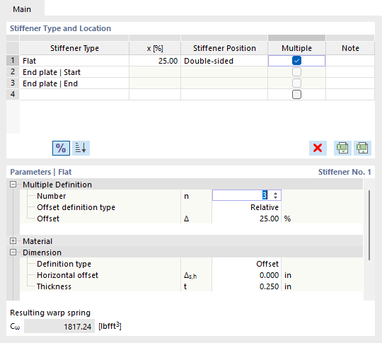
Parameters
In the dialog section below, you define the main properties of the stiffener. The parameters refer to the entry selected in the Stiffener Type and Location table. Information on the material and dimensions of the stiffener is usually required.

You can use the “Offset” definition type to define the width of the stiffener with reference to the cross-section contour: A horizontal offset Δs,h = 0 adjoins the stiffener between the outer edges. If you switch to the “Size” option in the list, you can also specify the width b directly.
In order to take into account the stiffener in the steel design, the Consider stiffener checkbox needs to be activated in the “Design Add-ons” category. Depending on the design standard, this option is not available for all stiffener types. It may be necessary to classify the plasticity of the stiffener.
Warping Restraint
If the Torsional Warping (7 DOF) add-on has been activated, the member transverse stiffeners are used to define warping restraints when calculating members with 7 degrees of freedom. More information can be found in the chapter Member Transverse Stiffeners of the add-on manual.
When using member transverse stiffeners for steel design, the resulting warping restraints spring stiffness is only displayed as information. There is no automatic transfer to the input of nodal supports in the dialog boxes Effective Lengths or Boundary Conditions.